International Research Journal of Engineering and Technology (IRJET)
e-ISSN: 2395-0056
Volume: 08 Issue: 06 | June 2021
p-ISSN: 2395-0072
www.irjet.net
A COMPARATIVE STUDY OF CAUSEWAYS AND CULVERTS Prajakta S. Deshpande1, Prof. P. K. Pasnur2 Student Civil Engineering Department, JSPM’S ICOER, Wagholi, Pune. Civil Engineering Department, JSPM’S ICOER, Wagholi, Pune. ---------------------------------------------------------------------***--------------------------------------------------------------------1P.G
2Professor
Abstract – Floods are the most critical among all the
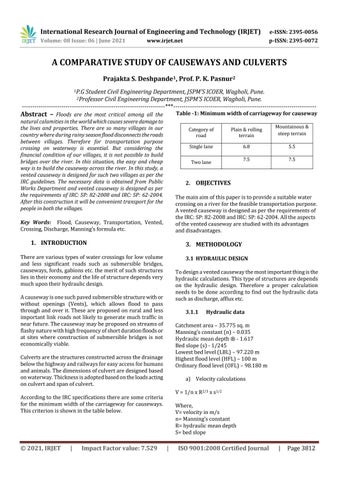
Table -1: Minimum width of carriageway for causeway
natural calamities in the world which causes severe damage to the lives and properties. There are so many villages in our country where during rainy season flood disconnects the roads between villages. Therefore for transportation purpose crossing on waterway is essential. But considering the financial condition of our villages, it is not possible to build bridges over the river. In this situation, the easy and cheap way is to build the causeway across the river. In this study, a vented causeway is designed for such two villages as per the IRC guidelines. The necessary data is obtained from Public Works Department and vented causeway is designed as per the requirements of IRC: SP: 82-2008 and IRC: SP: 62-2004. After this construction it will be convenient transport for the people in both the villages.
Single lane
6.8
5.5
7.5
7.5
The main aim of this paper is to provide a suitable water crossing on a river for the feasible transportation purpose. A vented causeway is designed as per the requirements of the IRC: SP: 82-2008 and IRC: SP: 62-2004. All the aspects of the vented causeway are studied with its advantages and disadvantages.
3. METHODOLOGY
There are various types of water crossings for low volume and less significant roads such as submersible bridges, causeways, fords, gabions etc. the merit of such structures lies in their economy and the life of structure depends very much upon their hydraulic design.
3.1 HYDRAULIC DESIGN To design a vented causeway the most important thing is the hydraulic calculations. This type of structures are depends on the hydraulic design. Therefore a proper calculation needs to be done according to find out the hydraulic data such as discharge, afflux etc.
A causeway is one such paved submersible structure with or without openings (Vents), which allows flood to pass through and over it. These are proposed on rural and less important link roads not likely to generate much traffic in near future. The causeway may be proposed on streams of flashy nature with high frequency of short duration floods or at sites where construction of submersible bridges is not economically viable.
3.1.1
Hydraulic data
Catchment area – 35.775 sq. m Manning’s constant (n) – 0.035 Hydraulic mean depth ® - 1.617 Bed slope (s) - 1/245 Lowest bed level (LBL) – 97.220 m Highest flood level (HFL) – 100 m Ordinary flood level (OFL) – 98.180 m
Culverts are the structures constructed across the drainage below the highway and railways for easy access for humans and animals. The dimensions of culvert are designed based on waterway. Thickness is adopted based on the loads acting on culvert and span of culvert.
a) Velocity calculations V = 1/n x R2/3 x s1/2
According to the IRC specifications there are some criteria for the minimum width of the carriageway for causeways. This criterion is shown in the table below.
Impact Factor value: 7.529
Mountainous & steep terrain
2. OBJECTIVES
1. INTRODUCTION
|
Plain & rolling terrain
Two lane
Key Words: Flood, Causeway, Transportation, Vented, Crossing, Discharge, Manning’s formula etc.
© 2021, IRJET
Category of road
Where, V= velocity in m/s n= Manning’s constant R= hydraulic mean depth S= bed slope
|
ISO 9001:2008 Certified Journal
|
Page 3812