1 minute read
Aspect

Volume: 08 Issue: 05 | May 2021 www.irjet.net p-ISSN: 2395-0072
2. Meshing
Advertisement
Finite Element Analysis, calculations are done only at a finite number of points, andthen for the entire surface results are calculated using interpolation [10]. In order to perform an analysis, the degrees of freedom must be finite. The Finite element technique involves meshing. By meshing, we reduce the degrees of freedom frominfinite to finite [11].
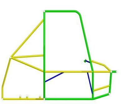
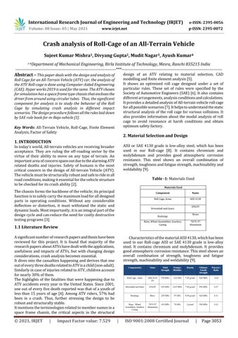
Fig -2.1: Full Vehicle Assembly
For the meshing of the roll cage, a 2D element type was used [12]. Thesteps involved were:
Geometry Clean up • The geometry was imported in Hyper Works2019. • To ensure connectivity of the mesh, all the free edges were removed, and errors post-importing the geometry were rectified.
Splitting • The entire roll cage was split according to the three different cross-sections of the comprising tubes. • The properties were updated respectively after splitting.
Element SizeSelection • The element size was chosen by analyzing the small piece of the tube under certain boundary conditions by decreasing the element size in each iteration. • The convergence in results wasobserved, andthe optimum size was chosen.
Mesh Generation • The mesh was generated under quality constraints for the best possible results. • After meshing, a quality check was done, and failed elements or portions were diagnosed.
Mesh Refining • In this phase of meshing, all the failed portions were manually corrected. Also, the point of junctions that had more stress flow were finely meshed to increase theaccuracy. Fig -2.2: Roll Cage-Top View
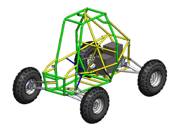
Fig -2.3: Roll Cage-Side View
Fig -2.4: Roll Cage-Front View
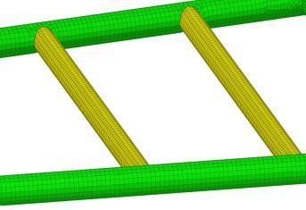
Fig -2.5: Seat Mount