2 minute read
3 Hidden

from IRJET- Parameter Estimation of Three Phase Induction Motor with Hybrid Soft Computing Techniques
VOLUME: 08 ISSUE: 05 | MAY 2021 WWW.IRJET.NET P-ISSN: 2395-0072
not depend or is less dependent on the starting values. The genetic approach is such a stochastic method [16-19]. It mimics the procedure of natural progress in real time. Genetic algorithm (GA) has been used in the past for parameter estimation of the TPIM [20-22].
Advertisement
IV. QUANTUM GA
Advancements in modern science have led from conventional to quantum computing with improved calculation time, labour and memory requirements; the need for non-polynomial complex problems. Several real time problems can be solved by genetic approach, but not with good efficiency. Hence, the present work concentrates on a Quantum Genetic Approach (QGA). QGA adapts ideas of Quantum bits (Q-bits) and its superposition. The usefulness and worthiness of QGA is used to train a GNA. Q-bit is the fundamental construction block of Qcalculation [23-24]. QGA contains group of Q-bits. The QGA population is modified by different operators to optimize the results [25]. A GNAtrained using QGA (Q-GNA) is used in this workfor parameter estimation of the TPIM.
V. Q-GENETIC ALGORITHM TRAINED GNA
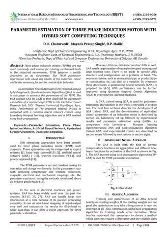
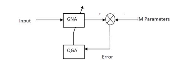
Schematic diagram of a Q-GNA is shown in Fig. 2, in which QGA is used for training. The advantageof QGA as training algorithm is that it is a stochastic learning algorithm and hence there is no need to calculate the error gradient (or derivative of error) as in the case of standard back propagation algorithm or its variants. Pseudo-Code for a Q-GNAis given below.
Fig-2: Schematic diagram of Q-GNA

Fig-3: TPIM Equivalent Circuit In the following section the above mentioned tools have been used for the parameter estimation of the TPIM.
VI. DETERMINATION OF EQUIVALENT CIRCUIT PARAMETERS OF AN INDUCTION MOTOR IN THE LAB
A delta connected TPIM is energized by balanced three phase, 415V, 50 Hz AC supply through a three phase autotransformer. To determine the equivalent circuit parameters of the TPIM, voltage, current and power of the TPIMare measured under the standardzero shaft loadand blocked rotor test conditions, using a voltmeter, ammeter and two watt-meters. Speed of the TPIM is quite close to synchronous speed (i.e. slip is nearly zero) in the no-load test. Parameters of the common TPIM equivalent circuit, Fig. 3, are computed using the well-known procedure in the laboratory. In Fig. 3,
Zo -no load impedance in ohms,
Ro -no load resistance in ohms,
Xo -no load reactance in ohms. Zb-equivalent impedance in ohms, Rb-equivalent resistance in ohms = r1+r2’, r1-Stator resistance in ohms r2-Rotor resistance in ohms referred to stator side Xb-equivalent reactance in ohms = x1+x2’. x1-Stator reactance in ohms x2-Rotor reactance in ohms referred to stator side
VII. PARAMETER ESTIMATION USING ANA, BP-GNA AND Q-GNA
Parameters calculated from the open circuit and blocked rotor tests are used as input for the training of an ANA, a BP-GNA and Q-GNA. These trained neural networks are