5 minute read
Motor load 12 V


Volume: 08 Issue: 03 | Mar 2021 www.irjet.net p-ISSN: 2395-0072
main objective behind the project was deploying an petrol powered unmanned aircraft for spraying. Their spray application rate is around 10 to 50 liter per hectare with 2 to 5 hectare per hour. Huang et al. [8] developed a spray system of unmanned aerial vehicle which have vector control in the remote areas which is accurate and site specific. They used two rotor motion’s unmanned autonomous vehicles. SR200 which is gasoline powered and SR20 which is battery powered. According to them their system is best suited for small crop plots with more site specific accuracy. Madhu et al. [9] proposed design of quad-copter for pesticide spraying with the objectives like reducing labor required, reducing system size and ease the spraying method. They used ardupilot mega 2.8 flight controller board and flysky transreceiver circuit. Meivel et al. [10] demonstrate the quad copter using flight controller this ad pilot control all operation which commanded by user. Authorused X cross configuration in quad copter configuration. This quad copter net payload was 4 kg to navigate that UAV GPS system was usedSprayer controlled by RF transmitter remote which is operated by user.Prasad Reddy et al. [11] proposed the system HAV which controlled by radio controller and spray kept continuously on which waste lots of fertilizer.Patel et al.[12] demonstrate the Quadcopter for agriculture surveillance in which the author. Used an infrared camera for taking image. In this image temperature sensing of plants by infrared thermography is done. Then using image disease is detected and for that specific area fertilizer are spraysover it. Kedari et al. [13] developed a Quadcopter which is used for pesticides spraying and this quad-copter is handle by an android application.
Advertisement
3. HARDWARE USED
3.1 Electronics speed controller (ESC):
Electronics speed controller isused to regulate the speed of electric circuit. ESC regulates the speed obtained from joystick, throttle level and manually input signal.
Fig -1: 30A Hobby Wing Fly fun brushless ESC
ESC generates three high frequency signals with different controllable phase continually to keep the motor turning. These ESC are able to push current of 30 amperesandcan push current up to 40 amperes for ten seconds based on voltage output. It can handle speeds up to 210,000 rotations per minute (RPM).
3.2 Brushless DC motor (BLDC):
Brushless DC motor is outer runner motor which is specially made for quad-copter and multirotor. These BLDC motors can run at maximum efficiency at 15 amp. of current and can handle currents of up to 18 amp. for up to sixty seconds. The maximum rpm per volt is 980 kpv and the maximum amount of power the motors can handle is 200 watts. These motors are also relativelylight, weighing about 500 grams.
Fig -2: A2212 electric brushless motor
It is 1400Kv motor. Feature of the motor is 3.2 mm hardened still shaft , dual ball bearingand has 3.5 mm gold spring male connector is already attached and include three female connector for speed control . It provides high performance super power and brilliant efficiency i.e.80% 30 A electronics speed controller can be used to drive motor.
3.3 Radio Receiver:
It receives 2.4 GHz signal from transmitter It has 10 channels that are independent to receive the signal from transmitter and send it to the controller to further processing.It has low current consumption and excellent receiver selectivity along withblocking performance. It has current consumption less than 40 mAandworks on 5 V power supply.

Volume: 08 Issue: 03 | Mar 2021 www.irjet.net p-ISSN: 2395-0072

Fig -3: Spectrum DX7S receiver (left) and transmitter (right)
3.4 MPU 6050:
MPU 6050 sensor has combination of accelerator and gyroscope chip .It has 16 bit analog to digital conversion hardware channel to each other it catches x, y and z channels at the inn same time. MPU6050 Sensor combine 3 axis accelerometers and 3 axis gyroscope on same silicon chip It is together with on board digital motion processor which process 6 axis motion fusion algorithm, I2C bus is used to interface with controller
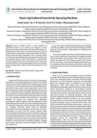
3.5 Lithium polymer batteries (LIPO):
Lithium polymer batteries are generally used as power sources in many electric modelers. It offers high energy storage ratio, weight ratio and high discharge rate LIPO battery is in a single cell 2.2 V to in a pack in cells is connected in series 37 V . F or Quad –copter 3 cells are connected in series as one parallel which give us 12 V Supply. It has4 stagesandfully automatic charging process which is controlled by MCU. It has 100% full loadburn-in test it has high efficiency, long and high reliability.
Fig -4: Battery and Balancer
3. SYSTEM DEVELOPMENT
In the quad-copter,term quad means four that means four motor are used in this system. Mainly there are two typesare available in quad-copter, one is ‘+ type configuration’ and second is ‘x type configuration’. For ourmodel,we used x type configuration .The Quad-copter module turns on by remote which is remotely located far away. The system mainly divided into two part i.e. transmitter and receiver. Objective of oursystem is to spray insecticide in 100 meter squarearea with the help of quad-copter and it is activated by module which is in placed in user location advantage of this system is quad-copter is activated by user with help of module and wireless communication is done between transmitter and receiver
In control
Panel Transmitter side
2.4 GHz
Fig -5: Block diagram of transmitter section
Figure 5 shows the block diagram of transmitter section In the transmitter section user have a remote to control the system which generated a signal according to movement of switch on remote. In the input side potentiometer is varies between 0 to 5 kΩ It gives signal to the ADC i.e. Analog to digital converter. It has 10 bit resolution. As per input given to the ADC the value is convert into 1 byte, Transmitter transmits the signals in the form of channels. No. of channels are transmitted through transmitter the transmitter section consist of control panel in which mechanical switches, joystick is including. Transmission rate of the transmitter is 2.4 GHz.
Figure 6 shows the block diagram of radio receiver section whichconsists of RF 2.4 GHz, BLDC, GPS, Compass, ATMEGA 2560 and water spray unit. It receives the signal through 2.4 GHz RF signal in form of string. In that string the channel is separate by 5 bytes. The channel is pitch, roll tthrottle, yaw, pump, an inertial measurements unit recognizes the difference in pitch, roll and saw used by gyroscope. IMU unit consist of gyroscope and accelerometer sensor.
Transmitter control assists the measurement sensor like gyroscope and accelerometer as per input send to signal to the electronics speed controller GPS is used to show the location and compass sensor shows direction It hold the position x,y axis Sensor give the signal to the controller It controls System .Controller gives 20 Ma current and single phase PWM to the electronics speed controller