13 minute read
2 Climate data collection

Volume: 08 Issue: 02 | Feb 2021 www.irjet.net p-ISSN: 2395-0072
(SAH) is needed for heating the process air supplied by the blower.
Advertisement
India is one of the major cashew nut producers and exporters. The overall cashew production in the world is 4,152,315 metric tons per annum. In that, India contributes about 6,8,000metric tons of cashew nut per annum (Food and Agriculture Organization, 2012). Tamil Nadu contributes about 9 % of the cashew production in which Cuddalore contributes around 47% i.e. 22,046 metric ton per annum [3].
Cashew processing comprises 8 steps like drying of raw cashew nut, Steaming, Cutting and Separation of shell, Drying of Kernel, Kernel cooling, Peeling of Kernel, Grading and Packing [4]. Among the eight steps in the cashew processing industry (which uses electric dryer for drying), the drying of cashew kernel is an energy intensive process which consumes around 575.64 MJ/1000 kg of raw nuts/180 kg batch [4]. The small scale farmers can produces around 800 kg of cashew nut per annum. They can rarely adopt the fossil fuel powered dryer due to its large initial and running cost. In order to overcome the limitations of the fossil fuel powered dryers the solar dryer can be used instead of it for drying the cashew nut.
2. MATERIAL AND METHODOLOGY 2.1 Material
The following were the materials which were utilized for the design consideration of forced convection updraft solar dryer. Absorber Plate -The absorber plate should be capable of retaining more solar energy and should have high thermal conductivity. The effectiveness of the solar collector mainly depends on the properties of the absorber plate. It should be coated with black paint to increase the absorptance of the absorber. Here, aluminium with 4 cm thickness was used as the absorber plate over copper due to its cost efficient and high corrosion resistance.
Cover plate (glass) –The cover plate’s main purpose is to lower the convective heat losses from the top of the solar collector. It should have a higher transmittance of solar radiation with low absorptance for high efficiency and should not deteriorate with time. The Glass was used as cover plate. Some plastic material could also use but it will deteriorate shortly. Here, the glass plate with 4mm is used because of its higher efficiency. Enclosure – It was mainly used to enclose all the components of the solar collector. Steel, aluminium, fiberglass and wood are some of the examples of enclosure. It also lowers the heat losses from the bottom of the solar collector. Generally, a layer of insulator is placed at the bottom of the absorber plate to reduce the heat loss. Insulator – It was used to lower the heat loss from the solar air heater. Here, timber was used as an insulator because of its low thermal conduction of 0.1442 W/mK. Desiccant – The desiccant has the higher potential to absorb/adsorb high moisture content from the processing air which is required for uniform and efficient solar drying. The desiccant will undergo two process cycles, 1. Adsorption/Absorption 2. Regeneration. During the first cycle it will absorb/adsorb moisture from processing air and during the second cycle the regeneration of desiccant material will be taking place under certain conditions.
Here, the silica gel was selected as the desiccant. The volume of the drying chamber was calculated as 35,400” in cubic inch. In general, 1 unit of desiccant can absorb 3 grams of water vaporat 20 % RH and 6 grams of water vaporat 40% of RH at 77 ᵒC. 1 unit of is equal to 32-33 grams of desiccant. The Silica gel can absorb moisture at maximum capacity of 35 % byits weight when exposed at 25 ᵒC and 80% RH. Therefore, the total unit required for the calculated volume of the drying chamber was 30 units, which means approximately 1 kg of Silica gel was needed. The quantity of desiccant used should be higher than the required rather than low amount. Galvanized wire mesh was used for covering the entry and exit of the air in the solar collector and drying chamber to prevent the entry of insects and rodents into the dryer. The timber of 5 mm thickness was used as a separator for desiccant from the drying chamber. Nails and glues. Hinges and handle for the drying chamber door. Black paint for higher absorption and thermal conductivity of the absorber plate. Galvanized wire mesh for the trays on which the cashew kernels are placed.
2.2 Climate data collection
The indirect solar dryer was designed for the location Cuddalore, Tamil Nadu (India) with Longitude of 79.533 ᵒE and Latitude of 11.7046 ᵒN. Cuddalore is a moderate climate district with hot summer and cold winter. The available solar radiation all-over the year on flat surfaces in Cuddalore was found to be 582 W/m2 [5]. With the tilt angle of 21.7046ᵒ towards south direction of the solar collector, the total solar radiation available on the titled surface was calculated as 613 W/m2. The above mentioned geographical details needed for the design were collected from PV syst software from Meteonorm 7.3.
Volume: 08 Issue: 02 | Feb 2021 www.irjet.net p-ISSN: 2395-0072
2.3 Design Procedure
In this section, the given equations were considered for designing of solar collector, drying chamber and desiccant chamber on the estimation of drying 20 kg of cashew nut.
Design Input parameters
The below given table consist of the design input parameters for the solar dryer,
Table -1: Gives the input parameter for the design of solar dryer
Location
Material
Design Input Parameters
Cuddalore [11.7046 ᵒN, 79.533ᵒE] Cashew Nut
Loading rate, mp [kg/day] 20
Initial Moisture Content, mi, [%] d.b 13
Final Moisture Content, mf, [%] d.b ≤5
Ambient air temperature, tam [ᵒC] 27.7
Ambient relative humidity, RHam [%] 74.2
Maximum allowable temperature, tmax [ᵒC]
Drying time (sunshine hours), t [hours] 70
9
Solar irradiance, Ib [MJ/m2/day] 18.68
Wind speed, Ws [m/s] 4.6
Collector efficiency, ɳ[%]
Vertical distance between two adjacent tray, d [cm] 20
15
The quantity of moisture(Mw)to beremoved from 20 kg cashew kernel can be determined from the below given equation [6];
Mw = mp (mi –mf) (1)
(100-mf) Where,Mw= the quantity of moisture to be removed from the cashew kernel(kg), mp = mass of the cashew nut (kg), mi = initial moisture content on wet basis (% w.b.), mf = final moisture content on wet basis (% w.b.). Therefore, 7 % of the moisture has to be removed from the 20 kg of cashew kernel i.e. 1.415 kg.
The total quantity of heat needed to reduce the moisture to the predetermined level was calculated from the following equation [6];
Q = Mw × hfg (2) Q = Quantity of heat needed to evaporate water (kJ), M�� = mass of water evaporated from cashew nut (kg), hfg= Latent heat of vaporization of water from the cashew nut surfaces (kJ/kg), Tp = Product temperature in [ᵒC] (wet bulb temperature of the ambient air).
The latent heat of vaporization[7]; hfg = 4.186 × 103×(597 –0.56Tp) (3)
With the latent heat of vaporization of 2456 kJ/kg, the total quantity of heat required was calculated as Q = 3476 kJ.
The total heat energy needed was calculated based on the equation given below [6]; E = M × (hf-hi) × t (4) Where; M = mass flow rate ofair, (kg/hr),hf ,hi = final and initial enthalpy of drying and ambient air respectively, t= drying time in hours.
The total heat energy needed was 4763.2 kJ with the mass flow rate of 3.65 kg/hr and the total amount of air required was 32.90 kg.
The volumetric flow rate was calculated with the wind velocity of 0.2 m/s, air gap height (h) of 0.05 m and width (w) of the solar collector was 1 m and air density of air as 1.225 kg/m3 from the below given equation [8];
Vf = V × h × w= 0.01 m3/sec (5)
Therefore, the total area of the collector was calculated from the following equation [9], AC = E (6) Ib× ɳ
The area of the solar collector is, AC = 1.3 m2 with an efficiency of 20 % of SAH.
The total volume of the cashew nut in trays in the drying chamber was 0.033 m3 with bulk density of cashew of 590 kg/m3. The length of the tray was 0.75 m.
From the following equation the total energy transmitted and absorbed by the solar collector was given [8]; IC × AC × (τα) = QU + QL +QS (7)
Where, QS is the energy stored which was considered as negligible i.e QS = 0, τ= 0.86, α = 0.9
Therefore, the overall heat losses co-efficient from the solar collector was UL = 3.249 W/m2 oC withuseful gain as 459.09W. The heat removal factor (FR) was1.0011.
Volume: 08 Issue: 02 | Feb 2021 www.irjet.net p-ISSN: 2395-0072
Energy and Mass balance were calculated. The hot air admitted inside the dryer was assumed to have an inlet temperature of 65 ᵒC with a humidity ratio of 0.046 kg/kg (with RH of 30 %).Mass balance results concluded that the exhaust air from the dryer should be at 37 ᵒC with 0.052 kg/kg humidity ratio (with RH of 80%). The above informationwasreferred from the psychrometric chart.
2.4. Description of Solar dryer:
The forced convection indirect mode solar dryer was designed for the location of Cuddalore (11.7046 ᵒN & 79.535 ᵒE), Tamil Nadu, India. The solar dryer was designed for the volume of 20 kg of cashew kernels. The solar dryer mainly consist of three components like solar collector, drying chamber, desiccant chamber. On basis of the volume of the product being dried, the area of solar collector required for the 20 kg cashew 1.3m2with width (1.3m) and length (1 m) 20% efficiency. The dimensions of the drying chamber was (0.75× 0.5 × 1.5) m high equipped with 10 trays of wire mesh and hinge doors.
Table -2: Shows the consolidated outcomes from the design of the solar dryer
Design outcome
Component Specification
Area of Collector, m2 1.3
Solar collector, m (1.3×1×0.13)
Absorber plate, m
Glass cover thickness, m (1.3×1×0.04)
(1.3×1×0.004)
Insulation material, m
Solar drying chamber, m
Air vent area, m Plywood (1.3×1×0.012)
Plywood (1.3×1×0.012)
(0.75×0.5×1.5)
Number of trays, m2 0.05
Distance between each tray, cm 15
3. CFD RESULT 3.1 Geometry Creation
For modeling of solar air heater, Ansys design modeler was used. Geometry of the solar flat plate collector consists of an aluminium absorber plate, single transparent glazing, and side walls.
3.2 CFD Model
CFD model was studied for detailed analysis of heat transfer and temperature increment in the solar air heater. The CFD software will provide numerical solutions of differential equations used in heat transfer and fluid flow analysis.
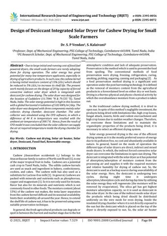
The geometry of the model was extracted and meshed using HyperMesh. Linear tetrahedron mesh was created with nodes of 24,957 and elements of 1,30,062.
Numerical simulation was completed using pressure based solver in steady state. The RNG k-Ɛ turbulence model with standard wall function was used. Good results were shown by the RNG k-Ɛ turbulence model of fluent for internal flows. For simulating radiation heat transfer, Discrete Transfer Radiation Model (DTRM) was used and solar load was applied to it through a solar calculator for the location of design with constant diffuse and direct solar radiation. According to the weather conditions of that day all other required parameters weregiven.
3.3 Boundary Condition
Boundary conditions were applied according to the flow conditions on the computational domain. The boundary condition was specified for the inlet air (“Inlet velocity”) and made it constant. The inlet air temperature was varied according to the ambient temperature recorded. The side walls were considered as opaque adiabatic walls and all the material boundaries were considered opaque. Values of wall roughness and wall height wereconsidered default for this analysis. Glazing is considered as semi-transparent with appropriate values of absorptivity and transmissivity.
4. RESULT AND DISCUSSION 4.1 Simulation Result
The CFD model of solar air heater design was studied with the geographical details of the location Cuddalore (latitude of 11.7046o N and longitude of 79.533o E) with specified boundary conditions. The current location is a moderate climate district with an availability of solar radiation for 6 months yearly and 11 hours of sunshine hours on daybasis. The inlet temperature value was the ambient temperature which was referred from the PV syst software.
Fig -1: Solar Air Heat
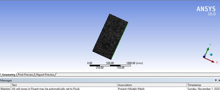
The temperature contours on absorber plate from top of solar air heater were shown in figure 2. This evident that the absorber temperature in solar air heater having a difference
Volume: 08 Issue: 02 | Feb 2021 www.irjet.net p-ISSN: 2395-0072
of 44K. On this side of absorber, the solar radiations were directly falling through transparent glazing.
Fig- 2: shows the temperature contours on absorber from top of solar air heater
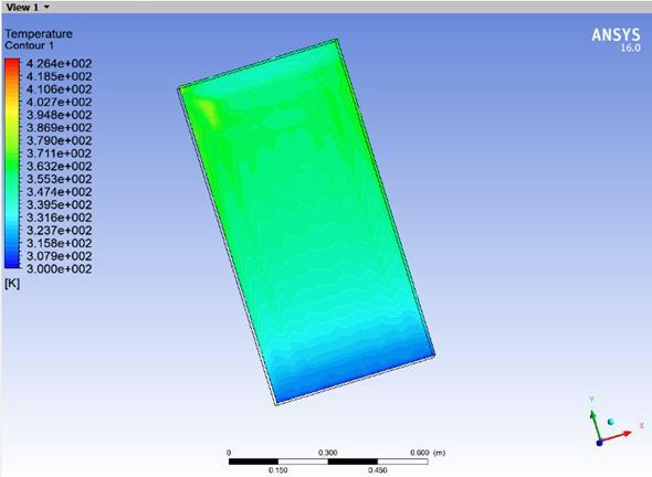
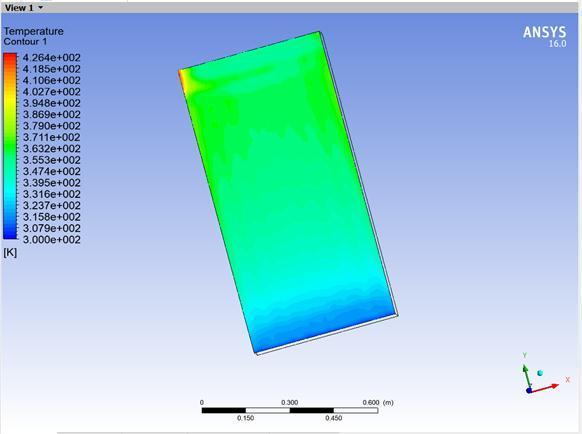
The temperature contours on glazing were shown in figure 3. It shows temperature variation from 300 K to 384K, starting from inlet of the solar air heater to outlet slots of air respectively.
Fig- 3: shows the temperature contours on glazing
From these results, it was evident that the designed solar collector for 20 kg capacity solar dryer has the ability to supply the temperature difference of 44 K inside the drying chamber. The solar collector and drying chamber would result with very high temperature than the ambient during the mid-day of the day while the sun is overhead. So, the efficiency of the solar collector would expect to be high at that time.
5. CONCLUSIONS
The following conclusionswere established at the end of the result, viz., Theforced convective indirectsolar dryer was designed for drying cashew kernel from the initial moisture content 13 % (d.b.) to final moisture content up to or less
than 5 % (d.b.) for the volumetric flow rate of 0.01 m3/sec of air The desiccant was decided to have as a backup source for the indirect typesolar dryer. As the properties of the air-vapor mixture were very important in controlling the rate of drying of the product being dried, the psychrometric chart was important for reference. It was mainly useful in determining humidity ratios of the air at the entry and exit of the drying chamber.
The economic analysis was done for the 20 kg capacity indirect type solar dryer, which gives a feasible result with a 1.2 payback period and 54 % of rate of return. The work was mainly focused on benefiting economically the small scale farmers, by using the renewable energy for the drying application in cashew nut processing. The future work of the project shall be extended to, a. The forced convective indirect typesolar dryer could be fabricated with the outcomes of the design calculation with low cost material.
b. The experimental evaluation of the solar dryercould be carried out with the experimental values. c. Two different types of desiccant could be used for study to know which is suitable for drying the cashew kernel.
REFERENCES
[1] UNECE STANDARD DDP-1 concerning the marketing and commercial quality control of cashew kernels: INC
International Nut and Dried Fruit Council, 2015. [2] Sahay K M and Singh K K, 2013, “Unit Operations of
Agricultural Processing”, Vikas Publishing House PVT
LTD. [3] P Murugamani and Dr. G Ravi: An assessment on cashew nut processing in Cuddalore district, Tamil Nadu:
Volume:1; No:1: International Journal of Business and
Economic Research November-2015. pp 01-09.
ISSN:2455-3921. [4] S Dhanushkodi, V H Wilson and K Sudhakar: Energy analysis of cashew nut processing agro industries: a case study: Bulgarian Journal of Agricultural Science, 22 (No 4) 2016, 635-642 Agricultural Academy. [5] Jan Remund, Esther Salvisberg, Stefan Kunz:
METEONORM Version 3.0 (1997): PV syst software. [6] EL-Amin Omda Mohamed Akoy, Mohamed Ayub Ismail,
E1-Fadil Adam Ahmed and W.Luecke: Design and construction of a solar dryer for mango slices. [7] Maundu Nicholas Musembi, Kosgei Sam Kiptoo, Nakajo
Yuichi: Design and analysis of solar dryer for mid latitude region: Volume 100, November 2016, Pages 98110. [8] Chandan Thakuria: A design and construction of a solar drying system for mushroom preservation:
Interantional Research Journal of Engineering and
Technology (IRJET) e-ISSN: 2395-0056 Volume: 05
Issue: 05| May-2018 p-ISSN: 2395-0072.