6 minute read
I. INTRODUCTION


Advertisement
Prathmesh Pudke1 , U. S. Chavan2
1M.Tech Student, Mechanical Engineering dept., VIT, Pune, India 2Professor and Assistant Head of Academics, Mechanical Engineering dept., VIT, Pune, India ----------------------------------------------------------------------*** -----------------------------------------------------------------------Abstract - Excavators are considered as earthmoving working speed. The material considered for the equipments and generally used for excavation process. excavator boom is Hardox400. During the process unknown large amount of resistive forces offered by the terrain, stones to the bucket teeth adversely Hardox is also known as high strength steel with a great affect on the excavator parts and may fail during excavation combination of hardness and toughness. Hardox has the process. Design engineer has a challenge for robust design yield strength of 1000 MPa[3]. of earth moving equipments which can work against unpredicted forces and under critical working condition. Thus, designers should provide not only a better design of parts that has maximum reliability but also minimum weight and cost, keeping design safe under all operating conditions. In this paper, Finite Element Analysis (FEA) tool is used for analysis and modifications of excavator boom. A modified design is proposed having rib structure with reliability. A 3D model of a boom is drawn by reverse engineering of existing structure in CATIA V5R19, Hypermesh 12.0 is used for meshing, and Ansys R15.0 will be used for solutions.
Keywords – FEA, Boom, Rib structure, modification.
I. INTRODUCTION
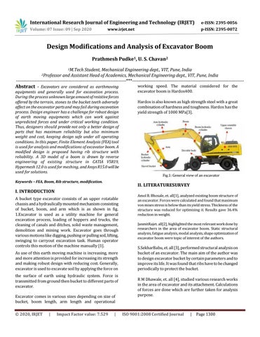
A bucket type excavator consists of an upper rotatable chassis and a hydraulically mounted mechanism consisting of bucket, boom, and arm which is as shown in fig. 1.Excavator is used as a utility machine for general excavation process, loading of hoppers and trucks, the cleaning of canals and ditches, solid waste management, demolition and mining work. Excavator goes through various motions like digging, pushing or pulling soil, lifting, swinging to carryout excavation task. Human operator controls this motion of the machine manually [1]. As use of this earth moving machine is increasing, more and more attention is provided for increasing its strength and making robust design with reducing cost. Generally, excavator is used to excavate soil by applying the force on the surface of earth using hydraulic system. Force is transmitted from ground then bucket to different parts of excavator. Excavator comes in various sizes depending on size of bucket, boom length, arm length and operational Fig.1: General view of an excavator
II. LITERATURESURVEY
Amol B. Bhosale, et. all[1], analyzed existing boom structure of an excavator. Forces were calculated and found that maximum von mises stress is below than its yield stress. Thickness of the structure was reduced for optimizing it. Results gave 36.4% reduction in weight.
JanmitRajet. all[2], highlighted the most relevant work done by researchers in the area of excavator boom. Static structural analysis, fatigue analysis, modal analysis, shape optimization of excavator boom were topic of interest of the authors.
S.SekharBabu, et. all [3], performed structural analysis on bucket of an excavator. The main aim of the author was to design excavator bucket by certain parameters and to improve its life. It was found that ribs have to be changed
periodically to protect the bucket. R M Dhawale, et. all [4], studied various research works in the area of excavator and its attachment. Calculations of forces are done which are further taken for analysis purpose.
International Research Journal of Engineering and Technology (IRJET) Volume: 07 Issue: 09 | Sep 2020 www.irjet.net e-ISSN: 2395-0056 p-ISSN: 2395-0072
This paper is important for researchers who are working in the field of finite element analysis of excavator.
AiminJiet. all [5], a method of integrated design of boom and analysis is put forward by considering all the problems in in development of actual product and working process of boom. Integrated design and analysis includes parametric design of excavator boom along with database design, mid surface extraction, static structural analysis. Simplification in structure is done based on parametric calculations.
Bhaveshkumar P Patel, et. all [6],has done the analysis on all the excavator components like bucket, boom, arm, swing link. Stresses and deformation were found out. With this , analysis of excavator taking welding consideration is done in which strength of the material for the welding should be less than the strength of the base metal.
Bhaveshkumar P Patel, et. all [7], provides a platform for analyzing and optimizing backhoe excavator attachment. In this, boom was modeled as a flexible body by using NASTRAN and the joint reaction forces of a rigid model and a flexible model are compared.
Gaurav K Mehta, et. all [8], found out force acting on each part of excavator linke bucket, boom, arm by static force. Analysis method by considering different operating conditions. It was found that critical condition for mechanism is where the maximum digging force acts. Each component was considered as free body for carrying force acting on it.
III. PROBLEMSTATEMENT
Excavators are subjected to high corrosive effects and loads. The excavator mechanism must even work under unpredictable operating conditions. Poor strength properties of the excavator parts like boom, arm and bucket limit the life of the excavator. Therefore, excavator parts should be robust enough to cope with caustic operating conditions of the excavator. The skilled operator is unaware of condition of road, soil parameter and sand force transmitted from soil during excavation process. These forces should consider for better design of tools, other parts of excavators, and for planning trajectory motion. Excavator has a cyclic motion during excavation. Because of this repetitive nature of work, cyclic stress are developed in the parts of excavator. In today’s world, weight is one of the major concern while planning and designing any machine parts. So for reducing the overall price further as for smoothing the performance of machine, modification is required. Analysis for weight reduction of boom to save material cost and fuel economy throughout the excavation operation under safe loading condition is needed [4, 6, 7]
IV. OBJECTIVES
This project, which will become alternate design for boom, comprise of rib structure to withstand high stresses developed during unpredictable working condition.
1.
2. Structural analysis which determines the area under high stress using FEA. Reduction in material which will reduces weight of structure by modification and ultimately reduces basic and operating cost.
V. METHODOLOGY
Steps followed for analysis of complete assembly of excavator are as follows
A. Analysis of existing model
1. 2. 3.
4. Reverse engineering of existing model. Generation of 3D model in CATIA V5R19software. Meshing of assembly, applying connections etc in Hypermesh12.0 Analysis of the assembly is done on AnsysR15.0 to
Predictthe stresses area developed on surface of boom of excavator which is then considered for modification.
B. Analysis of modified model
1.
2. Modification is done in form of iterations by reducing thickness of plates and by adding ribs structure in boom for each iteration and CAD model is done. Analysis is done for each iteration of modified model to check maximum scope of weight reduction.
C. D. Fabrication ,testing Validation (software and experimental)
VI. ANALYSIS OF EXISTING MODEL
1 CAD modelling Dimensions are taken through reverse engineering i.e. through manual calculations. CAD model of bucket, link, boom and arm is done. Fig.2 shows assembly in which components are arranged in such way that maximum digging force will act on bucket.