International Research Journal of Engineering and Technology (IRJET)
e-ISSN: 2395-0056
Volume: 07 Issue: 07 | July 2020
p-ISSN: 2395-0072
www.irjet.net
Comparative Investigation of 7-level Cascaded Multilevel Inverter using Multicarrier Level Shifted PWM Techniques Priyanka Meena1, Kapil Kansal2, Dr. Ahmed Hasan Khan3, Anil Kumar Sharma4 1Mtech
Scholar, JIT Jaipur Professor, JIT Jaipur 3Professor, JIT Jaipur 4Asst. Professor, JIT Jaipur 1-4Dept. of electrical Engineering, Jaipur Institute of Technology and Group of Institutions, Jaipur, Rajasthan, India ----------------------------------------------------------------------***--------------------------------------------------------------------2Asst.
Abstract - This manuscript presents the achieved efforts
Classification of Multilevel Inverter:
on 1-ϕ 7-level cascaded H-bridge multilevel inverter. To cheer the quality of 7-level CHBMLI output parameters primarily THD and switching losses, multicarrier level shifted technique is consider for controlling the gate pulse of 7level CHBMLI and the complete analysis of THD for 7-level is done. This work is performed and results are validated using MATLAB/SIMULINK.
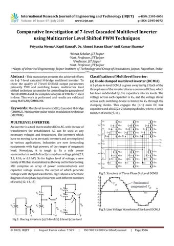
(a) Diode clamped multilevel inverter (DC MLI)
Keywords: Multilevel Inverter (MLI), Cascaded H-Bridge (CHBMLI), Multicarrier pulse width modulation technique (MCPWM).
A 3-phase 6-level DCMLI is given away in Fig 2 Each of the three phases of the inverter shares a common DC bus, which has been subdivided by five capacitors into six levels. The voltage across each capacitor is Vdc, and the voltage stress across each switching device is limited to Vdc through the clamping diodes. This engages the (n-1) main DC link capacitors and also Σ(2n-2) clamping diodes, where, n is the number of levels [9, 11].
MULTILEVEL INVERTER: An inverter is a tool that transfers DC to AC, with the use of transformers the rehabilitated AC can be used at any necessary voltages and frequencies. The inverters which have no moving parts are static inverters and are employed in various applications. Industries are now demanding equipments with high powers, of the ranges of megawatt level. Nowadays, it is tough to fix a sole power semiconductor switch directly to medium voltage grids (2.3, 3.3, 4.16, or 6.9 kV). So for higher level of voltage, a new family of MLI has materialized as the way out for functioning. MLI comprise an array of power semiconductors and capacitor voltage sources, the output of which generate voltages with stepped waveforms. Fig.1 shows a schematic diagram of one phase leg of inverters with different numbers of levels.[12, 13, 15]
Fig 2: Structure of Three Phase Six Level DCMLI
Fig 3: Line Voltage Waveform of Six-Level DCMLI Fig 1: One leg inverters (a) 1-level (b) 2-level (c) n-level
© 2020, IRJET
|
Impact Factor value: 7.529
|
ISO 9001:2008 Certified Journal
|
Page 3586