International Research Journal of Engineering and Technology (IRJET)
e-ISSN: 2395-0056
Volume: 07 Issue: 03 | Mar 2020
p-ISSN: 2395-0072
www.irjet.net
“Mathematical Modeling and Optimization of Process Parameters for En31 Material in EDM by Response Surface Methodology” Anant Nagnath Patwari1, Sawale J.K.2 1Department 2
of Mechanical Engineering, MGM’s College of Engineering, Nanded.
Professor, Department of Mechanical Engineering, MGM’s College of Engineering, Nanded.
---------------------------------------------------------------------***----------------------------------------------------------------------
Abstract - Electrical Discharge Machining (EDM) is one of
the most accurate manufacturing processes available for creating complex or simple shapes and geometries within parts and assemblies. EDM works by eroding material in the path of electrical discharges that form an arc between an electrode tool and the work piece. EDM manufacturing is quite affordable and a very desirable manufacturing process when low counts or high accuracy is required. The EDM system consists of a shaped tool or wire electrode, and the work piece. The work piece is connected to a power supply. To create a potential difference between the work piece and tool, the work piece is immersed in a dielectric (electrically non-conducting) fluid which is circulated to flush away debris. In this dissertation work optimization problem for En31 material has been solved to satisfy requirements of productivity in EDM operation. Experiments on die sinking EDM have been conducted using Response surface design using various process control parameters like discharge current (Ip), voltage (V) and pulse on time (Ton) which are varied in three different levels. Material Removal Rate (MRR), Tool wear rate (TWR) and surface roughness (SR) have been measured for each experimental run. Problem has been formulated in maximization of MRR (in order to increase productivity) and minimization of tool wear and surface roughness (in order to increase quality). The optimum values have been determined with the help of Doptimal plot and ANOVA table is used to find the significance of input parameters. Commercial grade EDM oil has been taken as dielectric fluid. MINITAB software has been used for mathematical modeling of MRR for different materials. Key Words: Discharge Current (Ip)1, Voltage (V)2, Pulse On Time (Ton)3,Material Removal Rate (MRR)4, Tool Wear Rate (TWR)5 And Surface Roughness (SR)6 etc.
1. INTRODUCTION Electric discharge machining is a thermo-electric non-traditional machining process. Material is removed from the work piece through localized melting and vaporization of material. Electric sparks are generated between two electrodes when the electrodes are held at a small distance from each other in a dielectric medium and a high potential difference is applied across them. Localized regions of high temperatures are formed due to the sparks occurring between the two electrode surfaces. Work piece material in © 2020, IRJET
|
Impact Factor value: 7.34
|
this localized zone melts and vaporizes. Most of the molten and vaporized material is carried away from the interelectrode gap by the dielectric flow in the form of debris particles. To prevent excessive heating, electric power is supplied in the form of short pulses. Spark occurs wherever the gap between the tool and the work piece surface is smallest. After material is removed due to a spark, this gap increases and the location of the next spark shifts to a different point on the work piece surface. In this way several sparks occur at various locations over the entire surface of the work piece corresponding to the work piece-tool gap. Because of the material removal due to sparks, after some time a uniform gap distance is formed throughout the gap between the tool and the work piece. If the tool is held stationary, machining would stop at this stage. However if the tool is fed continuously towards the work piece then the process is repeated and more material is removed. The tool is fed until the required depth of cut is achieved. Finally, a cavity corresponding to replica of the tool shape is formed on the work piece.
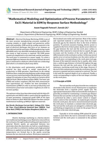
1.1 Principle of EDM The tool and the work piece form the two conductive electrodes in the electric circuit. Pulsed power is supplied to the electrodes from a separate power supply unit. The appropriate feed motion of the tool towards the work piece is generally provided for maintaining a constant gap distance between the tool and the work piece during machining. This is performed by either a servo motor control or stepper motor control of the tool holder. As material gets removed from the work piece, the tool is moved downward towards the work piece to maintain a constant inter-electrode gap. The tool and the work piece are plunged in a dielectric tank and flushing arrangements are made for the proper flow of dielectric in the inter-electrode gap. Typically in oil die-sinking EDM pulsed DC power supply is used where the tool is connected to the negative terminal and the work piece is connected to the positive terminal.
ISO 9001:2008 Certified Journal
|
Page 1386