International Research Journal of Engineering and Technology (IRJET)
e-ISSN: 2395-0056
Volume: 06 Issue: 08 | Aug 2019
p-ISSN: 2395-0072
www.irjet.net
Modeling & Analysis of a 100cc I.C. Engine Connecting Rod Alok Yadav1, Dr. L.P. Singh2, Shivani3 1M.
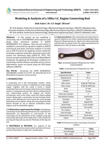
Tech Student, Production & Industrial Engg. (Mechanical Engineering Dept.), SHUATS, Allahabad, India Professor, Production & Industrial Engg. (Mechanical Engineering Dept.), SHUATS, Allahabad, India 3M. Tech Student, Production & Industrial Engg. (Mechanical Engineering Dept.), SHUATS, Allahabad, India ---------------------------------------------------------------------***---------------------------------------------------------------------2.1 Input parameters: The connecting rod model which is Abstract - In this project we are modeling a used for analysis is of a 100cc commercial motorbike (Bajaj connecting rod in SOLIDWORKS 2018 software and Discover). Measurements for which were taken practically doing static structural analysis in ANSYS with the help of a Caliper Scale. The engine specifications of WORKBENCH 19.2 software. Thus the part which is Bajaj Discover 100 are below in the table. modeled is converted into igs file to import in ANSYS work bench and static structural analysis is carried out at 400 N of force by applying various materials including composite materials, materials used in this project are aluminum alloy (2024-T6, 7075- T6), structural steel and 6092/SiC/25p-T6 Al Metal Matrix Composite. By applying the boundary conditions on connecting rod the unknown variables such as stress, Fig.1. Actual photograph of Bajaj Discover 100cc deformation, strain are found using the FEA based Connecting Rod. software (ANSYS). 2Associate
Table -1: Specifications of Bajaj Discover 100.
Key Words:
Connecting rod, ANSYS WORKBENCH, SOLIDWORKS, Al 2024-T6, Al 7075- T6, 6092/SiC/25p-T6 Al Metal Matrix Composite, Structural Steel.
1. INTRODUCTION A connecting rod is the intermediate member which connects a piston to a crank or crankshaft in a reciprocating engine. Together with the crank, it forms a simple mechanism that converts reciprocating motion into rotating motion. A connecting rod may also convert rotating motion into reciprocating motion, its original use. Earlier mechanisms, such as the chain, could only impart pulling motion. Being rigid, a connecting rod may transmit either push or pull, allowing the rod to rotate the crank through both halves of a revolution. Today, the connecting rod is best known through its use in internal combustion piston engines, such as automobile engines.
1.1 Dimension requirement for design: In designing a connecting rod, the following dimensions are required to be determined: (a) Dimensions of cross-section of the connecting rod, (b) Dimensions of the crankpin at the big end and the piston pin at the small end, (c) Size of bolts for securing the big end cap and (d) Thickness of the big end cap.
2. MATERIALS & METHOD: For analysis of the connecting rod, previous study models and data with some practical information is taken into consideration.
Š 2019, IRJET
|
Impact Factor value: 7.34
|
Specification
Value
Compression Ratio
9:1
Displacement
94 cc
Cylinders
1
Max. Power
8 bhp @ 7500 rpm
Max. torque
8 Nm @ 5000 rpm
Bore
47 mm
Stroke
54 mm
Valves per cylinder
2
Fuel delivery system
Carburetor
Fuel type
Petrol
Ignition
Digital CDI
Spark Plugs
2 per cylinder
Cooling system
Air cooled
No. of gears
4
Gear box type
Manual
Transmission type
Chain drive
Clutch
Wet multiplate
Table -2: Dimensions of the connecting rod used for analysis. Dimension
Value
Overall length
120 mm
Max. width
38 mm
ISO 9001:2008 Certified Journal
|
Page 189