INTERNATIONAL RESEARCH JOURNAL OF ENGINEERING AND TECHNOLOGY (IRJET)
E-ISSN: 2395-0056
VOLUME: 06 ISSUE: 08 | AUG 2019
P-ISSN: 2395-0072
WWW.IRJET.NET
Low VSWR Circularly Polarized Dielectric Resonator Antenna Array Fed by Cavity Backed SIW PENUGUDURU NARESH1, A. MALLIKARJUNA PRASAD2 1.2Department
of ECE, UCEK- JNTUK, Kakinada City, India ------------------------------------------------------------------------***------------------------------------------------------------------Abstract—To transmits the signals from one port to another port without any reflections the VSWR (Voltage Standing Wave Ratio) as much low as possible. To change the VSWR value in this paper the parallel conductivity plate in the ground plane of the designed DRA (Dielectric Resonator Antenna) is placed. The Circuit Complexity is reduced because of only one port is designed for entire designed DRA Array. For Mobile Communications VSWR value as low(<2) is preferred, The Results shows that the S11 Values at frequencies 8.3GHz, 9.5GHz, 10.8GHz and calculated VSWR values are 1.4, 1.8, 1.85 and radiation efficiency almost 90% over the operating bands. The array concept is used for the efficiency purpose and gain. The 4*4 DRA Array is designed. Whenever the Gain improved, the Directivity is also improved in particular Direction. The proposed design will be useful for the 5G Communications and millimeter wave applications. Keywords—Antenna Array, Substrate Integrated Waveguide(SIW), Dielectric Resonator Antenna(DRA), Voltage Standing Wave Ratio(VSWR). I. INTRODUCTION Now a days the wireless communication is famous as compared to the wired communications. For long distance purpose the wireless communication is necessary to reduce the cost. For clarity Information the Wired Communication is Used. There are different types of antennas are used for the different applications. For circular polarization[1] mainly Dielectric Resonator Antenna is used. To reduce the Dielectric Losses and Conductor Losses we introduce the Dielectric Resonator Antenna (DRA). In this Paper, the Substrate Integrated Waveguide (SIW)[3-6] technique is used. The SIW is also called as Post wall Waveguide or Laminated Waveguide [8]. For High Efficiency[6] purpose we use the DRA. For single Antenna, the gain may not be sufficient for the given application. So, that the concept of Array[5] is considered. The Antenna Behavior depends on Area, Dimensions, Shape and Materials etc. Maximum number of DRA antennas produce Circular Polarization. In general there are different Coupling Techniques are used, These are Slot Coupling[1], Probe Coupling and micro strip Coupling and Slotted SIW. A DRA is truncated into two isosceles triangles in a diagonal direction[7].
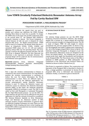
II. ANTENNA CONCEPT & DESIGN A. Design of DRA For antenna design purpose we use the HFSS (High Frequency Structural Simulator) Software. The hexagonshaped DR is formed by a square-shaped DR truncated with two isosceles triangles in a diagonal direction. The DR is made of Rogers TMM 10i with height H, relative permittivity 9.8, and loss tangent 0.002. As shown in Fig. (a). The length(ld) and width is adding some component to the (lc) of the hexagon shaped DRA is show in fig (b). The Substrate Integrated Waveguide is designed as per the given dimensions. DRA linear arrays are designed, by the series- fed slotted SIW[1]. For Feeding port, we use the coaxial probe feed. Apply the Boundaries and Excitations to the Designed DRA. The Theoretical values of the DRA is obtained in DWM modeler in HFSS software[9]. The Comparison of the Theoretical and Practical Values are obtained as shown in below Tabular form (1). This Project is organized as fallows, The construction and Operation of the Designed DRA is described in Section II. Then, a design guideline is presented. In Section III, the proposed DRA array is fabricated and measured for validation. Finally, a conclusion is given in Section IV. TABLE: 1 RESONANT FREQUENCIES FOR THE DRA ELEMENT IN FIG. 1 Theoretical Simulated
TE111(y) 9.9GHZ 9.2GHz
TE111 (x) 9.9GHZ 10.1GHz
Fig. (1). Geometry of the CP DRA element. (a)Exploded 3-D view. (b)Top view of the CP DRA element. (c) Top view of the slotted SIW. (Design parameters: a = 15.4, r = 0.7, p = 1, h = 1.5, H = 6, s0 = 1.9, l0 = 13, ld = 8, lc = 4.1, units: mm)
© 2019, IRJET
|
Impact Factor value: 7.34
|
ISO 9001:2008 Certified Journal
|
Page 1399