International Research Journal of Engineering and Technology (IRJET)
e-ISSN: 2395-0056
Volume: 06 Issue: 08 | Aug 2019
p-ISSN: 2395-0072
www.irjet.net
An Inductor based dc/dc Converter for Energy Harvesting Application with Low Input Voltage Sri. Arun Raj S.R1 1Assistant
Professor, Dept. of Electronics & Communication Engineering, UBDT College, Davangere, Karnataka, India. ----------------------------------------------------------------------***---------------------------------------------------------------------
Abstract - To operate portable devices in low input supply
voltages dc-dc converter are very useful and this type of devices are useful in energy harvesting application. In this paper is to boost low voltage dc-dc converter with inductor is used to produce high voltage supply voltage. In this paper input supply voltage is 500mV and it produce output voltage of 1.2 v. and by delivering a output current of 5.018µA and efficiency of about 34.44%. It is designed in 45nm CMOS technology by using Cadence Virtuoso software tool in this paper only single stage is used to produce output voltage of 1.2v and inductor were sized in 40µH to boost input voltage. Output power is 6.0216µW. Key Words: Converters, dc/dc power conversion, integrated circuit (IC) design.
1. INTRODUCTION Energy harvesting or power harvesting or energy scavenging is method in which energy is derived from external source like solar power, thermal energy, salinity gradients, kinetic energy and wind energy are captured and stored for small wireless autonomous devices, and these are used in wireless sensor networks and wearable electronics. Energy harvesting has the low quality like low voltages, low currents or both and it is often unsuitable for standard integrated devices for supplying. For example when thermopile is exposed to low temperature gradients it give the output high currents at low input voltages. A energy harvesting takes the energy from environment and converts that energy into electrical energy and gives the output or an unregulated source voltage. Energy harvesting are used in application like portable, handheld and implementable electronics. A dc/dc converter is a type of device like electronic circuit or electromechanical device, it converts from one voltage level to another voltage level of direct current (dc) and it is also type of power converter that convert power level range from very low that is small batteries to very high that is high voltage power transmission.
converter to step up voltage. The boost converter is used to increase the input voltage level from supply to high output voltage level to load. The boost converter is a class of switched mode power supply with containing two semiconductors that is diode and transistor and containing one storage element that is capacitor or inductor or both. In dc/dc converter output voltage is greater than source voltage. The boost converter is also called as step up converter and here p=vi, the output current is lower than source current. In dc/dc converter there are three stages they are Boosting stage, Timing circuit and Regulator part. In order to convert ultralow voltage to high voltage that is 300m to 1.2v, boosting stage requires two cascaded step up converter that is stepup1 and stepup2. In this paper the voltage is step up by using inductor. In this design input voltage is increased by inductor. In boosting stage transistor is used as a switch. Boost stage performs in two operations, that are when switch is open and switch is closed. The clock generator second stage is to generate 75% duty cycle, combining Dflip/flop these are used to generate 50% duty cycle.
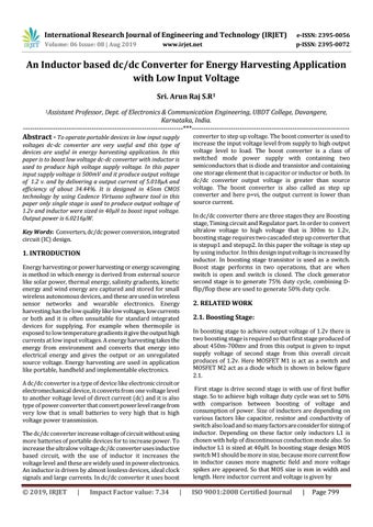
2. RELATED WORK 2.1. Boosting Stage: In boosting stage to achieve output voltage of 1.2v there is two boosting stage is required so that first stage produced of about 450m-700mv and from this output is given to input supply voltage of second stage from this overall circuit produces of 1.2v. Here MOSFET M1 is act as a switch and MOSFET M2 act as a diode which is shown in below figure 2.1.
The dc/dc converter increase voltage of circuit without using more batteries of portable devices for to increase power. To increase the ultralow voltage dc/dc converter uses inductive based circuit, with the use of inductor it increases the voltage level and these are widely used in power electronics. An inductor is driven by almost lossless devices, ideal clock signals and large currents. In dc/dc converter it uses boost
First stage is drive second stage is with use of first buffer stage. So to achieve high voltage duty cycle was set to 50% with comparison between boosting of voltage and consumption of power. Size of inductors are depending on various factors like capacitor, resistor and conductivity of switch also load and so many factors are consider for sizing of inductor. Depending on these factor only inductors L1 is chosen with help of discontinuous conduction mode also. So inductor L1 is sized at 40µH. In boosting stage design MOS switch M1 should be more in size, because more current flow in inductor causes more magnetic field and more voltage spikes are appeared. So that MOS size is mm in width and length. Here inductor current and voltage is given by
© 2019, IRJET
ISO 9001:2008 Certified Journal
|
Impact Factor value: 7.34
|
|
Page 799