International Research Journal of Engineering and Technology (IRJET)
e-ISSN: 2395-0056
Volume: 06 Issue: 08 | Aug 2019
p-ISSN: 2395-0072
www.irjet.net
DESIGN MODIFICATIONS IN CRYOGENIC PRESSURE RELIEF VALVE TO ELIMINATE SEAT LEAKAGE Kavali Saichaithanya1, Dr. B. Omprakash2, Dr. R. Ganapathi 3 1PG Research Scholar, 2 Assistant Professor. Internal Combustion Engines, Dept, of Mechanical Engineering 1, 2 Jawaharlal Nehru Technological University Anantapur College of Engineering (Autonomous), Anantapuramu, Andhra Pradesh, India 3Dept, of Mechanical Engineering, Anurag Engg College (Autonomous), Kodad, Telangana, India ---------------------------------------------------------------------***---------------------------------------------------------------------1Advanced
Abstract - Cryoliquids plays vital role in rocket engines,
transportation and storage of large masses of frozen food. Storage and transport of cryoliquids of very low temperatures is very difficult. In the pipe lines or the storage facilities that contain this kind of low temperature liquids must be equipped with more safety measure as the expansion ratios of this liquids is very large as 700 times. If this pressure exceeds the limits this may leads to burst in pipe lines. This is where safety pressure relief valve shows its importance. Thermal relief valve is designed to popup for reliving excess pressure from at a predetermined pressure and reseat after reliving the excess pressure from the segment. Thermal relief valves provided in most of cryo systems are metal to metal seated for ensuring leak tightness and are sized to relieve minimum flow rate of 300 SCFM of air. For metal to metal seated valves, attaining zero leakage or Class VI leakage classification is not possible due to surface finish limitations.
423°F to +400°F, which also makes them an ideal choice for labs and other facilities where nitrogen and other gases are supplied by boil-off from liquid gas storage tanks.
1.1 Functions of PRV Every industrial process system is designed to work against a certain maximum pressure and Temperature called its rating or design pressure. The law requires that when everything fails regardless of the built-in redundancies, there is still an independent working device powered only by the medium it protects. This is the function of the PRV, which, when everything else works correctly in the system, should never have to work.
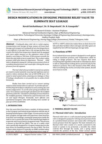
Studies have been carried out to convert existing metal to metal seated valves to soft seal. To provide soft seal – PCTFE (Polychlrotriflouro ethylene) to suit to existing disc and nozzle configuration. To use the same spring provided for the valve. Force balance and strength calculations for the modified geometry of the disc. Calculation of leakage pressure based on the modified geometry. Followed by experimental tests with air and Liquid Nitrogen. Eventually, more efficient and operational Cryogenic valve with standing more number of pop-ups will be established. Fig1.1: Traditional control loop
1. INTRODUCTION Over the years there have been a number of advancements in the Cryogenic and Industrial gas industries with the aim of keeping liquefied gases colder longer. At some point even the best cryogenic storage tanks will experience some heat flux from their surroundings, causing the temperature inside the tank to rise to a point that some of the liquefied gas begins to evaporate and reverts back to its gaseous state. This process is known as Boil-Off Gas (BOG). The use of a safety relief valve specifically designed for cryogenic temperatures is the best choice for handling pressure rise due to BOG. The first of these safety features is typically an ASME certified safety relief valve, which have an operating temperature range of -
2. THERMAL RELIEF VALVES
© 2019, IRJET
ISO 9001:2008 Certified Journal
|
Impact Factor value: 7.34
|
2.1 Thermal relief valve - Introduction Thermal relief valve is a self-actuated spring-loaded relief valve is designed to popup for reliving excess pressure from at a predetermined pressure and reseat after reliving the excess pressure from the segment. The basic elements of a thermal relief valve consist of a nozzle connected to the vessel or system to be protected, a movable disc which controls flow through the nozzle, and a spring which controls the position of the disc. Under normal system
|
Page 698