International Research Journal of Engineering and Technology (IRJET)
e-ISSN: 2395-0056
Volume: 06 Issue: 07 | July 2019
p-ISSN: 2395-0072
www.irjet.net
A Review: Microstrip Antenna Dilip Gupta1, Ashish Duvey2, Shweta Agrawal3 1M.Tech
Scholar, Dept. of Electronics & Communication, SRCEM Banmore, M.P, India Professor, Dept. of Electronics & Communication, SRCEM Banmore, M.P, India ---------------------------------------------------------------------***---------------------------------------------------------------------2,3Assistant
Abstract - In present scenario wireless communication is
constant of the substrate (εr) is typically in the range 2.2 ≤ ≤ 12 εr .
growing very fast, this communication is possible because of antennas. The performance of antenna plays vital role in communication systems. In wireless communication microstrip patch antennas are used as their results are very appreciable. This paper presents an over view of microstrip patch antenna, its uses, merits and demerits, common shapes of microstrip patch elements. Here important parameters of Microstrip patch antennas are explained that are essential for communication system. Key Words: wireless communication, microstrip patch antenna
Fig-2: Common shapes of microstrip patch antenna
1. INTRODUCTION
Microstrip patch antennas radiate primarily because of the fringing fields between the patch edge and the ground plane. For good antenna performance, a thick dielectric substrate having a low dielectric constant is desirable since this provides better efficiency, larger bandwidth and better radiation [2]. However, such a configuration leads to a larger antenna size. In order to design a compact Microstrip patch antenna, higher dielectric constants must be used which are less efficient and result in narrower bandwidth. Hence a compromise must be reached between antenna dimensions and antenna performance.
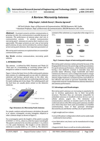
The antenna is defined by IEEE, Stutzman and Thiele [1] “That part of a transmitting or receiving system that is designed to radiate or receive electromagnetic waves”. Figure 1 shows the basic form of a Microstrip patch antenna that consists of a radiating patch on one side of a dielectric substrate and having a ground plane on the other side. Copper and gold is mainly used as conducting material used for patch making and of any shape. The radiating patch and the feed lines are usually photo etched on the dielectric substrate.
1.1 Advantages and Disadvantages Microstrip patch antennas are increasing in popularity for use in wireless applications due to their low-profile structure. Therefore they are extremely compatible for embedded antennas in handheld wireless devices such as cellular phones, pagers etc... The telemetry and communication antennas on missiles need to be thin and conformal and are often Microstrip patch antennas. Another area where they have been used successfully is in Satellite communication. Some of their principal advantages discussed by [2] and Kumar and Ray [3] are given below:
Fig.1 Structure of a Microstrip Patch Antenna For simply analysis and performance calculation, the patch is of square, rectangular, circular, triangular, elliptical or other common shape as shown in Figure 2.
• Light weight and low volume. • Low profile planar configuration which can be easily made conformal to host surface.
For a rectangular patch, the length L of the patch is usually 0.3333λ0 < L < 0.5 λ0 , where λ0 is the free-space wavelength. The patch is selected to be very thin such that t << λ0 (where t is the patch thickness). The height h of the dielectric substrate is usually 0.003 λ0 ≤ h ≤ 0.05 λ0. The dielectric
© 2019, IRJET
|
Impact Factor value: 7.211
• Low fabrication cost, hence can be manufactured in large quantities. • Supports both, linear as well as circular polarization.
|
ISO 9001:2008 Certified Journal
|
Page 1238