International Research Journal of Engineering and Technology (IRJET)
e-ISSN: 2395-0056
Volume: 06 Issue: 05 | May 2019
p-ISSN: 2395-0072
www.irjet.net
Analytical Study on Different Types of Steel Slit Dampers Akhil T Mani1, Shilpa Sara Kurian2 1Mtech
Student, Computer Aided Structural Engineering, SNGCE, Kadayirippu P.O Kolenchery, Kerala, India 2Assistant Professor, Civil Department, SNGCE, Kadayiruppu P.O, Kolenchery, Kerala, India ---------------------------------------------------------------------***----------------------------------------------------------------------
Abstract - The seismic resiliency of reinforced concrete (RC)
undergo inelastic deformation and dissipate seismic energy [1]. This paper presents an analytical study on different patterns of steel, including an angle of 45 degree slit, 30 degree slit, 15 degree slit, 0 degree slit and circular slit patterns, to examine the ductile behaviour and to identify the best steel geometry.
structures can be significantly improved by using hybrid coupling beams installed with metallic dampers. Inelastic deformation is concentrated in the shear link during a severe earthquake thus the damper yields first and absorbs a large amount of energy, protecting the RC part of the structure. This paper presents an analytical study on different steel slit patterns, including an angle of 45 degree slit, 30 degree slit, 15 degree slit, 0 degree slit and circular slit patterns, to examine the ductile behavior and to identify the best steel geometry. Non-Linear dynamic analysis is conducted in ANSYS workbench 16.1 to observe the cyclic behaviour of steel plates with different slit patterns. Peak load and displacement with corresponding time is observed for comparison. It was found that load carrying capacity and number of cycle’s increases in 15 degree steel slit as compared to other type of steel geometry. Key Words: Hybrid coupling beams, Metallic damper with slits, cyclic behaviour, dynamic analysis, shear link.
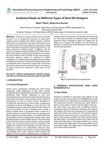
Fig -1: Replaceable steel coupling beam
1. INTRODUCTION 1.1 General Background
2. NUMERICAL INVESTIGATION USING ANSYS WORKBENCH 16.1
Recent major earthquakes including the 2010 Maule earthquake (Chile, Magnitude of 8.8), 2011 Tohoku earthquake (Japan, Magnitude of 9.0) and 2011 Christchurch earthquake (New Zealand, Magnitude of 6.3), have demonstrated that our built environment and infrastructure, Particularly in the urban context, need to be more resilient to earthquakes. In order to ensure minimal disruption to everyday life and business in urban society, prompt postearthquake recovery of buildings is a clear need [1]. The coupling beam plays as the first protection in the reinforced concrete structures. In order to dissipate more energy, a hybrid coupling beam is developed which consists of a metallic damper in series with the concrete coupling beam. The strength of the metallic damper is carefully selected so that the RC part of the coupling beam remains elastic, while all plasticity goes into the metallic damper. This mechanism protects the RC part from seismic damage. And the metallic damper can be quickly replaced once it is damaged. This significantly enhances the reparability of entire structure, making it possible to be immediately functional after earthquakes. Coupled wall systems are often used in highrise buildings due to their superior lateral strength and stiffness. In such a system, coupling beams are designed to
Š 2019, IRJET
|
Impact Factor value: 7.211
2.1 Base Model Numerical modelling of Steel plate with patterns of slit models were done using ANSYS 16.1 WORKBENCH, a finite element software for mathematical modelling and analysis. The dimensions of all the 5 specimens are same. Width of plate is 6 mm, depth is 150 mm and the length is 476 mm. The steel plates were given slots of different patterns, including an angle of 45 degree slit, 30 degree slit, 15 degree slit, 0 degree slit and circular slit patterns. For each plate an equal area of slots were driven out. The Analysis requires input data for material properties are as shown in Table 1. Figure 2 showing the modelled view of Steel with 45 degree slit angle. Figure 3 showing modelled view of Steel with 30 degree slit angle. Figure 4 showing modelled view of Steel with 15 degree slit angle. Figure 5 showing modelled view of Steel with 0 degree slit angle. Figure 6 showing modelled view of Steel with circular slit.
|
ISO 9001:2008 Certified Journal
|
Page 193