International Research Journal of Engineering and Technology (IRJET)
e-ISSN: 2395-0056
Volume: 06 Issue: 12 | Dec 2019
p-ISSN: 2395-0072
www.irjet.net
DESIGN, MANUFACTURING AND TESTING OF TRANSPARENT ACRYLIC PROTOTYPE OF HYDRAULIC BRAKE MASTER CYLINDER AKASH KHAMKAR1, ADITYA PACHUPATE2, VINAYAK PATIL3, SHUBHAM BADGUJAR4 1,2,3,4Student, Dept. of Mechanical Engineering, PCET’s Pimpri Chinchwad College of Engineering, Pune, India ----------------------------------------------------------------------***---------------------------------------------------------------------
Abstract – Safety has a prime importance in day to day life. Since, hydraulic brakes are the best safety feature for the vehicles; they are used in almost every vehicle available today on the road. Master cylinder is used to generate the hydraulic pressure inside the brake lines to apply the brakes. The purpose of this paper is to propose solution for testing the hydraulic brake master cylinder in an efficient way. This paper presents transparent acrylic brake master prototype as an efficient solution to analyze dynamic working of brake fluid inside the master cylinder and to evaluate failure causes leads to brake fluid leakage through the oil seals. Key Words: Hydraulic brakes, master cylinder, acrylic, prototype, testing, bleeding process
1. INTRODUCTION Braking system is an energy converting system which converts vehicle movement into heat while stopping the rotations of wheel. Generally, hydraulic brakes are used in every vehicle on the road where hydraulic pressure is used to create braking force on the brake disc which causes friction between brake pads and brake disc and vehicle stops. The brake master cylinder is hydraulic cylinder which generates pressure when pedal force is applied by the driver on the brake pedal. Since, we cannot see the dynamic working of piston and brake fluid inside the master cylinder, one cannot suggest the causes of seal wear and accumulation of air bubbles inside the cylinder. Hence, transparent acrylic cylinder body is proposed as the best solution to analyse and evaluate basic causes during the working of the brake master cylinder.
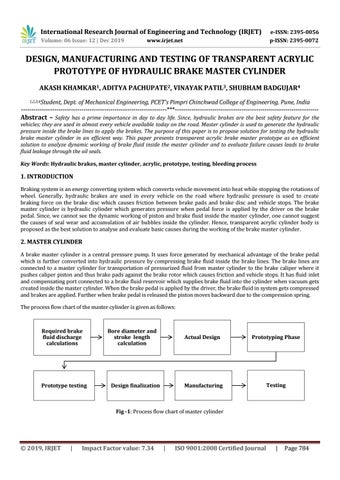
2. MASTER CYLINDER A brake master cylinder is a central pressure pump. It uses force generated by mechanical advantage of the brake pedal which is further converted into hydraulic pressure by compressing brake fluid inside the brake lines. The brake lines are connected to a master cylinder for transportation of pressurized fluid from master cylinder to the brake caliper where it pushes caliper piston and thus brake pads against the brake rotor which causes friction and vehicle stops. It has fluid inlet and compensating port connected to a brake fluid reservoir which supplies brake fluid into the cylinder when vacuum gets created inside the master cylinder. When the brake pedal is applied by the driver, the brake fluid in system gets compressed and brakes are applied. Further when brake pedal is released the piston moves backward due to the compression spring. The process flow chart of the master cylinder is given as follows:
Required brake fluid discharge calculations
Prototype testing
Bore diameter and stroke length calculation
Design finalization
Actual Design
Prototyping Phase
Manufacturing
Testing
Fig -1: Process flow chart of master cylinder
© 2019, IRJET
|
Impact Factor value: 7.34
|
ISO 9001:2008 Certified Journal
|
Page 784