International Research Journal of Engineering and Technology (IRJET)
e-ISSN: 2395-0056
Volume: 06 Issue: 11 | Nov 2019
p-ISSN: 2395-0072
www.irjet.net
ESTIMATION OF STRESS INTENSITY FACTOR FOR THE DIFFERENT CRACK MODES USING FINITE ELEMENT ANALYSIS P. Pavansai1, M. NagaRaju2, Mr. M. RAMESH3 1M.Tech
Student, Department of Mechanical Engineering, Chirala Engineering College, Chirala, Prakasam Dist. Andhra Pradesh 2Assistant Professor, Department of Mechanical Engineering, Chirala Engineering College, Chirala, Prakasam Dist. Andhra Pradesh 3Associate. Professor and Head, Department of Mechanical Engineering, Chirala Engineering College, Chirala, Prakasam Dist. Andhra Pradesh --------------------------------------------------------------------------***----------------------------------------------------------------------------
ABSTRACT:- The failure of cracked components is governed by the stresses in the vicinity of the crack tip. The singular stress contribution is characterized by stress intensity factors. The stress intensity factors depend on the geometry of the component and on loading condition. This paper addresses the evaluation of stress intensity factors (SIFs) of opening, and tearing modes for compact tension specimens for bonding homogeneous materials. The aim of this work is to find the optimal pre-cracked length, crack notch radius and crack notch angle in order to eliminate the effect of them on the SIF and then on the Fracture toughness. To achieve this goal, a three dimension finite element analysis (FEA) model using ANSYS program is constructed for specimens made of homogeneous materials such as stainless steel bonding with epoxy as a filler material. The effects of notch angle, notch tip radius and pre-crack length on the stress intensity factors are studied for different fracture modes. Keywords: FEA, Stress intensity factor & Method of separation of variables 1. Introduction to rivets
|
Impact Factor value: 7.34
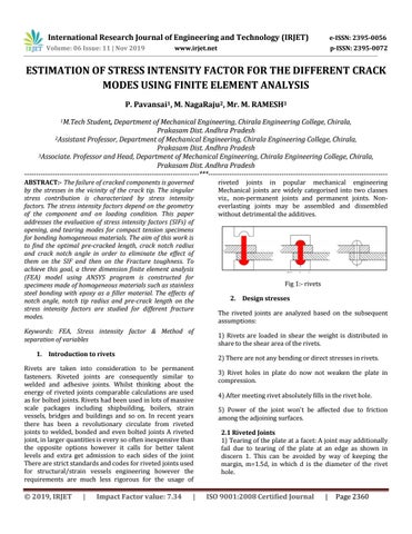
Fig 1:- rivets 2. Design stresses The riveted joints are analyzed based on the subsequent assumptions: 1) Rivets are loaded in shear the weight is distributed in share to the shear area of the rivets. 2) There are not any bending or direct stresses in rivets.
Rivets are taken into consideration to be permanent fasteners. Riveted joints are consequently similar to welded and adhesive joints. Whilst thinking about the energy of riveted joints comparable calculations are used as for bolted joints. Rivets had been used in lots of massive scale packages including shipbuilding, boilers, strain vessels, bridges and buildings and so on. In recent years there has been a revolutionary circulate from riveted joints to welded, bonded and even bolted joints A riveted joint, in larger quantities is every so often inexpensive than the opposite options however it calls for better talent levels and extra get admission to each sides of the joint There are strict standards and codes for riveted joints used for structural/strain vessels engineering however the requirements are much less rigorous for the usage of
Š 2019, IRJET
riveted joints in popular mechanical engineering Mechanical joints are widely categorised into two classes viz., non-permanent joints and permanent joints. Noneverlasting joints may be assembled and dissembled without detrimental the additives.
|
3) Rivet holes in plate do now not weaken the plate in compression. 4) After meeting rivet absolutely fills in the rivet hole. 5) Power of the joint won't be affected due to friction among the adjoining surfaces. 2.1 Riveted Joints 1) Tearing of the plate at a facet: A joint may additionally fail due to tearing of the plate at an edge as shown in discern 1. This can be avoided by way of keeping the margin, m=1.5d, in which d is the diameter of the rivet hole.
ISO 9001:2008 Certified Journal
|
Page 2360