International Research Journal of Engineering and Technology (IRJET)
e-ISSN: 2395-0056
Volume: 06 Issue: 10 | Oct 2019
p-ISSN: 2395-0072
www.irjet.net
STATIC AND FRACTURE ANALYSIS FOR AIRCRAFT FUSELAGE AND WING JOINT WITH COMPOSITE MATERIAL Mr. Singana Ayyavar Reddy1, Mr. D.L. Komalarao2 and Mr. M. Ramesh3 1M.Tech
Student , Department of Mechanical Engineering, Chirala Engineering College, Chirala, Prakasam Dist. Andhra Pradesh 2Associate Professor, Department of Mechanical Engineering, Chirala Engineering College, Chirala, Prakasam Dist. Andhra Pradesh 3Associate. Professor and Head, Department of Mechanical Engineering, Chirala Engineering College, Chirala, Prakasam Dist. Andhra Pradesh --------------------------------------------------------------------------***----------------------------------------------------------------------------
Abstract: Fracture mechanics provides a methodology for prediction, prevention and control of fracture in materials, components, and structures. Fracture mechanics analysis is the backbone of damage tolerant design. Objectives of fracture mechanics analysis are: (1) stress analysis of cracks to derive crack tip stress field equations and define crack tip stress intensity factors, (2) determination of SIF solutions as function of crack length, orientation and applied loads for a given geometry, (3) prediction of mixed mode fracture under static, dynamic, and sustained loads, (4) prediction of residual strength as a function of crack length. The focus of this paper is on fracture mechanics analysis of longitudinaland circumferential joints of aircraft fuselage structure with cracks. The loading is by internal pressure. Commercial FEA software ANSYS and a special purpose post-processing subprogram called 3MBSIF are used to determine mixed mode membrane and bending SIF solutions. Residual strength prediction is based on the use of strain energy density theory of fracture. Significant results of this study are graphically presented and discussed in this paper.
conjointly serves to position management and stabilization surfaces in specific relationships to lifting surfaces that is needed for craft stability and maneuverability. 1.1 Types of structures
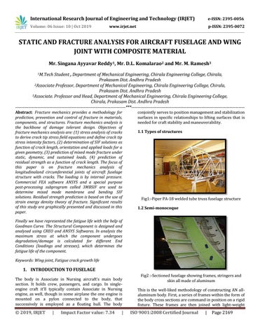
Fig1:-Piper PA-18 welded tube truss fuselage structure 1.2 Semi-monocoque
Finally we have represented the fatigue life with the help of Goodman Curve. The Structural Component is designed and analysed using CREO and ANSYS Softwares. In analysis the maximum stress at which the component undergoes degradation/damage is calculated for different End Conditions (loadings and stresses), which determines the fatigue life of the component. Keywords: Wing joint, Fatigue crack growth life
1. INTRODUCTION TO FUSELAGE The body is Associate in Nursing aircraft's main body section. It holds crew, passengers, and cargo. In singleengine craft it'll typically contain Associate in Nursing engine, as well, though in some airplane the one engine is mounted on a pylon connected to the body, that successively is employed as a floating hull. The body
Š 2019, IRJET
|
Impact Factor value: 7.34
|
Fig2 :-Sectioned fuselage showing frames, stringers and skin all made of aluminum This is the well-liked methodology of constructing AN allaluminum body. First, a series of frames within the form of the body cross sections are command in position on a rigid fixture. These frames are then joined with light-weight
ISO 9001:2008 Certified Journal
|
Page 2169