International Research Journal of Engineering and Technology (IRJET)
e-ISSN: 2395-0056
Volume: 06 Issue: 11 | Nov 2019
p-ISSN: 2395-0072
www.irjet.net
The Effect of Tooth Thickness on Root Stress of Internal Spur Gear Mechanism Tufan Gürkan Yılmaz1, Fatih Karpat2 1Department
of Mechanical Engineering, Bursa Uludag University & Bursa, Turkey of Mechanical Engineering, Bursa Uludag University & Bursa, Turkey ---------------------------------------------------------------------***--------------------------------------------------------------------2Department
Abstract - This study aims to enhance the load carrying capacity of the internal spur gear mechanism by making stress equal between pinion and internal gear by shifting standard thickness on pitch circle. As standard, this thickness value is half of pitch. Actually, it can be shifted if the total pitch value is equal to πm. To understand the effect of tooth thickness variation on stress, finite element analyses are implemented. When the thickness is on pitch circle, the root stress decreases. Specific thickness values which make maximum stress equal is determined. Besides, the total mechanism weight is decreased with this method. Key Words: Internal spur gear, tooth thickness, finite element analysis, bending stress, lightweighting 1. INTRODUCTION The internal spur gear mechanism is composed of internal and pinion gear. Internal spur gear tooth has bigger thickness on root zone that it is subjected to lower stress than pinion. This difference can be removed with decreasing thickness on pitch circle of internal gear and increasing thickness on pitch circle of pinion. The pinion shaper is the common generation tool of internal and pinion gear. The geometry of this cutter is similar to pinion gear just tip of cutter is sharpened to cut teeth. In literature, there are various publications about different kinds of tooth designs to decrease root stress. One of these methods is using asymmetric gear that it has different pressure angle on drive and coast sides. With increasing pressure angle, the stress levels decrease [1-2]. Yılmaz et al. investigated effect of changing cutter tip radius on external and internal spur gears. When tip radius is increased, the stress values decrease [3-4]. Another method is to use artificial curves. Spitas et al. offered circular curve to reduce stress. However it is just effective when tooth number is under the 17 [5]. Zou et al. conducted an optimization study to reach an optimum curve. With specified curve, the stress values decrease approximately 20% [6]. Using different tooth thicknesses from standard value is novel approach. Sekar and Muthuveerappan conducted finite element analysis to obtain the effect of tooth thickness on stress of external spur gear mechanisms. Balanced stress values are determined for given teeth number, pressure angle and profile shifting coefficient [7].
© 2019, IRJET
|
Impact Factor value: 7.34
|
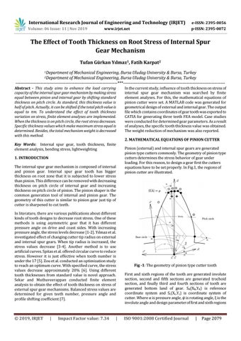
In the current study, influence of tooth thickness on stress of internal spur gear mechanism was searched by finite element analyses. For this, the mathematical equations of pinion cutter were set. A MATLAB code was generated for geometrical design of external and internal gear. The output file which contains coordinates of gear tooth was exported to CATIA for generating three teeth FEA model. Case studies were conducted for determined gear parameters. As a result of analyses, the specific tooth thickness value was obtained. The weight reduction of mechanism was also reported. 2. MATHEMATICAL EQUATIONS OF PINION CUTTER Pinion (external) and internal spur gears are generated pinion type cutters commonly. The geometry of pinion type cutters determines the stress behavior of gear under loading. For this reason, to design a gear first the cutters equations have to be set properly. In Fig.1, the regions of pinion cutter are illustrated.
Fig -1: The geometry of pinion type cutter tooth First and sixth regions of the tooth are generated involute section, second and fifth sections are generated trochoid section, and finally third and fourth sections of tooth are generated bottom land of gear. SR(XR,YR) is reference coordinate system and Sc(Xc,Yc) is coordinate system of cutter. Where α is pressure angle, ψ is rotating angle, ξ is the involute angle and design parameter of first and sixth regions
ISO 9001:2008 Certified Journal
|
Page 2079