International Research Journal of Engineering and Technology (IRJET)
e-ISSN: 2395-0056
Volume: 06 Issue: 11 | Nov 2019
p-ISSN: 2395-0072
www.irjet.net
1 GHz Inverse Filters using Operational Amplifier Bharath Kumara1, Palak Goel2, Pallavi Sharma3 1Asst.
Professor, Dept. of ECE, M S Ramaiah University of Applied Sciences, Bangalore, Karnataka, India Student, Dept. of ECE, M S Ramaiah University of Applied Sciences, Bangalore, Karnataka, India 3 B.E Student, Dept. of ECE, M S Ramaiah University of Applied Sciences, Bangalore, Karnataka, India ---------------------------------------------------------------------***---------------------------------------------------------------------2B.E
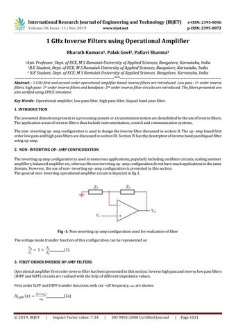
Abstract - 1 GHz first and second order operational amplifier based inverse filters are introduced. Low pass- 1st order inverse filters, high pass- 1st order inverse filters and bandpass- 2nd order inverse filter circuits are introduced. The filters presented are also verified using SPICE simulator. Key Words: Operational amplifier, low pass filter, high pass filter, biquad band pass filter. 1. INTRODUCTION The unwanted distortions present in a processing system or a transmission system are demolished by the use of inverse filters. The application areas of inverse filters thus include instrumentation, control and communication systems. The non- inverting op- amp configuration is used to design the inverse filter discussed in section II. The op- amp based first order low pass and high pass filters are discussed in section III. Section IV has the description of inverse band pass biquad filter using op-amp. 2. NON- INVERTING OP- AMP CONFIGURATION The inverting op amp configuration is used in numerous applications, popularly including oscillator circuits, scaling summer amplifiers, balanced amplifier etc, whereas the non inverting op- amp configuration do not have much applications in the same domain. However, the use of non- inverting op- amp configuration is presented in this section. The general non- inverting operational amplifier circuit is depicted in fig 1.
Fig -1: Non-inverting op-amp configuration used for realization of filter The voltage mode transfer function of this configuration can be represented as: __________(1) 3. FIRST ORDER INVERSE OP AMP FILTERS Operational amplifier first order inverse filter has been presented in this section. Inverse high pass and inverse low pass filters (IHPF and ILPF) circuits are realised with the help of different impedance values. First order ILPF and IHPF transfer functions with cut –off frequency, ωc are shown: ____________(2a)
© 2019, IRJET
|
Impact Factor value: 7.34
|
ISO 9001:2008 Certified Journal
|
Page 1111