International Research Journal of Engineering and Technology (IRJET)
e-ISSN: 2395-0056
Volume: 04 Issue: 09 | Sep -2017
p-ISSN: 2395-0072
www.irjet.net
Comparative Study of Delay Line Based Time to Digital Converter Using FPGA Zalak Soni1,, Arpit Patel2, Dipak Kumar Panda3, Amit Basu Sarbadhikari4 PG Student, Dept. of E.C. Engineering, Gujarat Technological University PG School, Gandhinagar, Gujarat, India 2, 3, 4 Scientist, Planetary Science Division, Physical Research Laboratory, Ahmedabad, Gujarat, India ---------------------------------------------------------------------***--------------------------------------------------------------------1
Abstract - Many time-of-flight (TOF) applications need
measurement of time difference between two events. A time to digital converter is suitable for these kinds of applications because it measures time difference between two pulses and gives time difference as a digital output code. However basic TDC needs much higher clock frequency to measure smaller time differences in terms of picoseconds. High clock frequency leads to major power dissipation and unstable clock which are not desirable. Different architecture of delay lines which can be used with TDC to measure smaller time interval with less clock frequency has been studied and compared in this paper. It is useful in improving performance of measurement. FPGA based TDC can be used because of fully digital structure of TDC and FPGAs provides flexibility and low cost. Key Words: Time to Digital Converter (TDC), Field Programmable Gate Array (FPGA), Vernier Delay line, Low Resolution, Time of Flight (TOF) applications, time interval measurement.
1. INTRODUCTION TDC has several applications in different engineering fields. TDC is useful in measurement of the velocity of the moving particles in many physics experiments, unknown fiber length, the thickness of the chemical coating on a substrate can also be measured using TDC[4]. In the field of particle and high energy physics, TDC is mostly used for requirement of precise time interval measurement. In electronics it gives advantage in utilization of measuring the time interval between two pulses. TDC is most important application in time of flight (TOF) application. TOF is a method used to measure distance between sensor and object, based on the time difference between the emission of signal and its return to the sensor, after being reflected by an object [2]. Application of medical, space, nuclear science also needed measurement between two events. In digital phase locked loop, TDC serves as phase detector. For meeting time requirements of different applications ASIC- based chips are can be designed but design of such chips is costly, complicated and time consuming. Field Programmable Gate Arrays (FPGAs) provide configurable logic blocks (CLBs) that can behave like any logic circuits. To implement variety of circuits, FPGAs provide very flexible way [7]. Therefore, Timing devices Š 2017, IRJET
|
Impact Factor value: 5.181
|
based on FPGAs are becoming very popular. It has several advantages like lower cost, and faster development cycle. It has some disadvantages like delay variation due to Process, voltage & control, unpredictable place & route and no direct control over delays. Circuit delays of FPGA devices are highly dependent on wiring and routing inside an integrated circuit, which is why manual placement and routing of signals is essential for accurate measurements. The resolution of measurement is also dependent on the technology used, and with more recent deep sub-micron technologies, higher resolution can be acquired.
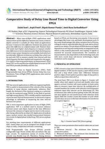
2. PRINCIPAL OF OPERATION A TDC converts a time interval between different pulses into digital numbers. A TDC has two inputs, a start which arrives first and a stop which comes later. Difference between positive edges of start pulse to positive edge of stop pulse is called as input time interval (Tin). The most basic TDC is as shown in figure 1. Counter will enable when start signal is arrived and disable when stop signal is arrived. Counter will count number of clock cycles taken to measure input time interval. By multiplication of counted numbers by counter with reference clock frequency unknown input time interval can be determined [9]. This architecture also called as direct gating. In this TDC, the start and stop signals are not synchronous with reference clock signal, while the counter counts the number of cycle which can introduce an error in the time information. Its waveforms are as given figure 2.
Fig -1: Counter based TDC (Direct gating) There are some parameters that needs to taken into account in TDC. 1. Minimum interval - The minimum time between consecutive pulses. 2. Minimum dead-time - The minimum time between the stop pulse and the next start pulse. ISO 9001:2008 Certified Journal
| Page 1169