International Research Journal of Engineering and Technology (IRJET) Volume: 04 Issue: 05 | May -2017
www.irjet.net
e-ISSN: 2395 -0056 p-ISSN: 2395-0072
Design of compensator for Servomechanism Ayush Chauhan1, Ashray Srivastava2, Vasundhara Sharma3 1 ,2,3student
Department of electrical engineering, Bharati vidyapeeth university college of engineering , Pune, Maharashtra, India ---------------------------------------------------------------------***--------------------------------------------------------------------Abstract— The objective of our project is to design the compensator for d.c. positional servo systems and stability analysis for frequency and time response using bode plot analysis. The proposed system is to gain the relative stability and improvement in transient response with the help of different compensators such as lag and lead compensators. Keywords—transfer function; system;control;feedback
lead
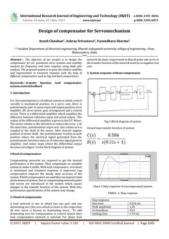
network the basic requirement is that all poles and zeros of the transfer function of the network must lie on negative real axis. 3. System response without compensator
compensator;
1. Introduction D.C. Servomechanism is a feedback system in which control variable is mechanical position. In a servo unit, there is potentiometer pair to sense input and output position, error amplifier ,DC servo motor, gear arrangement and a control circuit. There is a differential amplifier which amplifies the difference between reference input and actual output . The output of the differential amplifier is given to the D.C. Motor. The motor rotates in the direction to reduce the error. a At the same time , potentiometer wiper arm also rotates as it is coupled to the shaft of the motor. After desired angular position of motor shaft , the potentiometer reaches at such position where the electrical signal generated from the potentiometer becomes same as of reference signal given to amplifier. And motor stops where the differential output becomes zero.figure 1is the block diagram of system.
Fig-1:Block diagram of system Closed loop transfer function of system
2.Need of compensators
Step Response
1.4
sys_cl 1.2
Compensating networks are required to get the desired performance of the system. They compensate an unstable system to make it stable. With lead compensator, overshoot is minimized and transient response is improved. Lag compensators improve the steady state accuracy of the system. If both compensators are used they can improve total performance of system. Due to compensating networks poles and zeroes are introduced in the system which causes changes in the transfer function of the system. With this, performance specifications of the system may change.
Amplitude
1
0.4
0 0
Impact Factor value: 5.181
0.5
1
1.5
2
2.5
Time (seconds)
Chart-1:Step response of uncompensated system TABLE -1: Step response Step response Rise time Peak amplitude % Overshoot Settling time
A lead network is one in which has one pole and one dominating zero (the zero which is closer to the origin than all over zeros is known as dominating zero). To add dominating zero for compensation in control system then lead compensation network is selected. For phase lead
|
0.6
0.2
2.1Need of compensator
Š 2017, IRJET
0.8
|
0.226 sec 1.26 29.3 1.73 Sec
ISO 9001:2008 Certified Journal
| Page 2605