International Research Journal of Engineering and Technology (IRJET) e-ISSN: 2395 -0056 Volume: 04 Issue: 05 | May -2017
www.irjet.net
p-ISSN: 2395-0072
Comparative Study Of RCC Skew T-Beam Bridge Using Grillage Analogy Method Harish S. Rakaraddi 1, R. Shreedhar 2 Post-Graduate Student, Dept. of Civil Engineering, KLS Gogte Institute of Technology, Belagavi, India 2, Associate Professor, Dept. of Civil Engineering, KLS Gogte Institute of Technology, Belagavi, India ---------------------------------------------------------------------***--------------------------------------------------------------------1
Abstract-T-beam Bridge is a common choice among the designers for small and medium span bridges. In order to cater to greater speed and more safety to present day traffic, the modern highways are to be straight as far as possible. But the presence of skew in a bridge some time cannot be avoided due to constraints in fixing straight alignment. For the T- beam bridges with small skew angle, it is frequently considered safe to ignore the angle of skew and analyse the bridge as right bridge with a span equal to the skew span. However, T-beam Bridge with large angle of skew can have considerable effect on the behavior of the bridge especially in the short to medium range of spans. Hence an attempt is made to study the behavior of Tbeam skew bridges with respect to bending moment, shear force, torsion and deflections under standard IRC loadings. The skew angle chosen for study are 0˚, 15˚, 30˚, 45˚ and 60˚. The analysis carried out by grillage analogy method.
Keywords: TEE beam bridge deck, IRC 6, Grillage analogy method, Skew angle
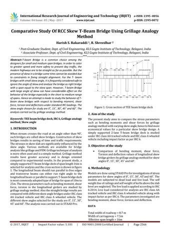
1. INTRODUCTION When stream crosses the road at an angle other than 90˚, such bridges are called skew bridges. Construction of skew bridges results in saving of time and traffic requirements. The stresses in skew slab are significantly influenced by the skew angle. Various methods are available for bridge analysis like grillage and FEM. Grillage technique of analysis is more often used and is a simple method. Grillage method results have greater accuracy and is design oriented compared to experimental results. In the present study, a simply supported T-beam bridge deck of span length 16m is selected for analysis and the cross section is shown in figure 1. The longitudinal beam should run parallel to free edges and transverse beams can either run right angle to the longitudinal beam or parallel to support. T-beam bridge deck is most commonly adopted type of bridge for span of 10m to 25m. The stress parameters such as bending moment, shear force, torsion in the longitudinal girders are studied by grillage analogy method. Also the straight bridge results are compared with different skew angle bridges under IRC class AA tracked vehicle and IRC class A wheeled vehicle. The different skew angles selected for the study are 0˚, 15˚, 30˚, 45˚ and 60˚. The analysis was carried out in STAAD Pro.
Figure 1. Cross section of TEE beam bridge deck
2. Aim of the study The present study aims to compare the stress parameters such as bending moments and shear forces by grillage analogy method with varying skew angle, hence to find more economical values for a particular skew bridge design. A simply supported 2-lane T-beam bridge deck is studied under IRC class AA tracked vehicle and IRC class A wheeled vehicle including impact factor as per IRC 6.
3. Objective of the study
Comparison of bending moment, shear force, Torsion and deflection values of longitudinal skew bridge girders by grillage analogy method for skew angles 0˚, 15˚, 30˚, 45˚ and 60˚.
4. Methodology Models are done using STAAD Pro for investigations of stress parameters for skew angles of 0˚, 15˚, 30˚, 45˚and 60˚. The models are subjected to dead load and live load. The self weight due of railings and self weight of kerbs above the slab level are neglected. The live load is applied according to IRC 6:2014, Live load considered for analysis are IRC class AA tracked vehicle and IRC class A wheeled vehicle along with impact factor as per IRC 6. The parameters investigated are bending moment, shear force, torsion and deflection. DATA Total width of roadway = 8.7 m Width of carriageway = 7.5m Effective span length = 16m
© 2017, IRJET
|
Impact Factor value: 5.181
|
ISO 9001:2008 Certified Journal
|
Page 2566