International Research Journal of Engineering and Technology (IRJET)
e-ISSN: 2395 -0056
Volume: 04 Issue: 04 | Apr -2017
p-ISSN: 2395-0072
www.irjet.net
Microstrip C-R Slotted WiFi Antenna Modified for X band Applications Nithin A Marattil1, Angel P Mathew2 1PG
Studnt, Dept. of ECE, ICET, Kerala, India Dept, of ECE, ICET, Kerala, India
2Professor,
---------------------------------------------------------------------***---------------------------------------------------------------------
Abstract - Recent research show that some parameters
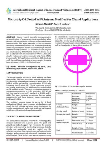
the antenna to the required frequency band. But, in addition to C-R slot two symmetric arcs are also etched from both sides of the circular patch for better accuracy. The required resonance frequencies are obtained by parameter variation such as changing the bridge width or position [2].
such as the shape of antenna patch and ground plane when geometrically altered produces changes in the return loss and resonant modes. This paper presents a circular rectangular microstrip antenna modified with the technique of inserting slots in the ground plane in order to alter the specific behavior in the resonant frequencies. The antenna has been designed and simulated using ANSOFT HFSS simulator. It make use of FR4 as substrate with dimensions 50mm×40mm×1.2mm. The circular rectangular antenna resonates at 2.4 and 5.5GHz frequencies for WiFi applications according to IEEE standards, while the modified ground plane version resonates through a band of frequency (9.92-11.46 GHz ) in X band Key Words: Circular rectangular(C-R) patch, Gain, Microstrip patch antenna, Return loss, VSWR
1. INTRODUCTION Circular-rectangular microstrip patch antenna has been presented for dual band in wireless communication systems [2]. Microstrip antenna has wide range of application in the field of mobile and satellite communication, RFID (radio frequency identification), GPS (global positioning system) and in radar applications. It is widely used because of its low profile and lightweight. There was a recent development in wireless communication in order to convert IEEE WLAN (wireless local area network) standards in 2.4GHz and 56GHz. This paper presents an antenna that can satisfy operations in both these frequency ranges, resonates at 2.4GHz and 5.5GHz.
Fig -1: Structure of Circular Rectangular Antenna Table -1: Design Geometry of CR Patch Antenna
The modified antenna design is purely for X band applications. X band radar frequency sub-bands are used widely in civil, military and government institutions for weather monitoring, air traffic control defense tracking and vehicle speed detection in law enforcement [1].
Parameters Resonant Frequency Dielectric Constant Length
Dimensions 2.4 GHz, 5.5GHz 4.4
Width
40mm
Circular patch
Radius of patch
16.8mm
Rectangular patch
Length
12.5mm
Width
22.59mm
Horizontal strip
3.25mm
Vertical strip
8.32mm
Length of strip
15.25mm
Width of strip
1.654mm
Ground /Substrate Plane
2. C-R PATCH AND DESIGN GEOMETRY Length of connecting strip
The basic antenna structure consists of a radiating patch, dielectric substrate and a ground plane. The patch and ground are made of copper. Fig.1 represents the antenna structure with microstrip line feeding technique. Initially circular and rectangular patch are created over the substrate, such that these two antennas are kept one inside the other and are connected using small conducting strips called bridges. These bridges have a great impact in tuning
© 2017, IRJET
|
Impact Factor value: 5.181
Feed
|
ISO 9001:2008 Certified Journal
50mm
| Page 3034