International Research Journal of Engineering and Technology (IRJET)
e-ISSN: 2395 -0056
Volume: 04 Issue: 04 | Apr -2017
p-ISSN: 2395-0072
www.irjet.net
Transmission Line Inspection Robot Muhammed Jabir O K1, Nayana K Francis2, Radhika K3 and Sneha Sajumon4 1234Student,
Dept. Of Electrical and Electronics, Mar Athanasius College of Engineering , Kerala, India
---------------------------------------------------------------------***---------------------------------------------------------------------
Abstract - The mobile robots equipped with inspection
sensors, instruments and communication devices are able to automatically perform on-line detection or inspection of mechanical or electrical failures without suspending power supply. The robot gathers the data of these transmission lines using various sensors which is sent to the control room by using the transceiver provided in the robot. The communication between the robot and control room takes place without wires using existing infrastructures utilizing RF technology or any other communication protocols. A short GSM based fault detection and location system was used to accurately indicate and locate the exact spot where fault has occurred.
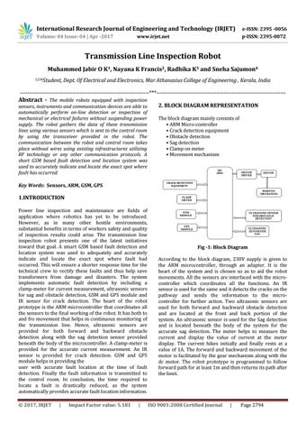
2. BLOCK DIAGRAM REPRESENTATION The block diagram mainly consists of • ARM Micro-controller • Crack detection equipment • Obstacle detection • Sag detection • Clamp on meter • Movement mechanism
Key Words: Sensors, ARM, GSM, GPS
1.INTRODUCTION Power line inspection and maintenance are fields of application where robotics has yet to be introduced. However, as in many other hostile environments, substantial benefits in terms of workers safety and quality of inspection results could arise. The transmission line inspection robot presents one of the latest initiatives toward that goal. A smart GSM based fault detection and location system was used to adequately and accurately indicate and locate the exact spot where fault had occurred. This will ensure a shorter response time for the technical crew to rectify these faults and thus help save transformers from damage and disasters. The system implements automatic fault detection by including a clamp-meter for current measurement, ultrasonic sensors for sag and obstacle detection, GSM and GPS module and IR sensor for crack detection. The heart of the robot prototype is the ARM microcontroller that coordinates all the sensors to the final working of the robot. It has both to and fro movement that helps in continuous monitoring of the transmission line. Hence, ultrasonic sensors are provided for both forward and backward obstacle detection along with the sag detection sensor provided beneath the body of the microcontroller. A clamp-meter is provided for the accurate current measurement. An IR sensor is provided for crack detection. GSM and GPS module helps in providing the user with accurate fault location at the time of fault detection. Finally the fault information is transmitted to the control room. In conclusion, the time required to locate a fault is drastically reduced, as the system automatically provides accurate fault location information. © 2017, IRJET
|
Impact Factor value: 5.181
|
Fig -1: Block Diagram According to the block diagram, 230V supply is given to the ARM microcontroller, through an adapter. It is the heart of the system and is chosen so as to aid the robot movements. All the sensors are interfaced with the microcontroller which coordinates all the functions. An IR sensor is used for the same and it detects the cracks on the pathway and sends the information to the microcontroller for further action. Two ultrasonic sensors are used for both forward and backward obstacle detection and are located at the front and back portion of the system. An ultrasonic sensor is used for the Sag detection and is located beneath the body of the system for the accurate sag detection. The meter helps to measure the current and display the value of current at the meter display. The current hikes initially and finally rests at a value of 1A. The forward and backward movement of the motor is facilitated by the gear mechanism along with the dc motor. The robot prototype is programmed to follow forward path for at least 1m and then returns its path after the limit.
ISO 9001:2008 Certified Journal
|
Page 2794