International Research Journal of Engineering and Technology (IRJET)
e-ISSN: 2395 -0056
Volume: 03 Issue: 02 | Feb-2016
p-ISSN: 2395-0072
www.irjet.net
NEW DESIGN APPROACH TO IMPLEMENT BINARY ADDER BY USING QCA K.Lavanya1, S.Ramanjinaik2 1
M.Tech,VLSI Design, Student, SRIT Engg.College, karanamlavanya0482@gmail.com. 2
Associate.Professor.in ECE, SRIT Engg.College,AP,India, ramanjivlsi@gmail.com.
---------------------------------------------------------------------***--------------------------------------------------------------------
Abstract : Now a day’s certain limit has specified for the
transistor count in IC’s. Hence to incorporate more number of transistors in a single die to increase computational capabilities a new gate has been implemented in this paper that overcomes the physical limit of the existing designs. The new technique implemented is quantum dot cellular automata (QCA), which is the design of logic modules in QCA.A new 128-bit adder is implemented which will be more efficient of delay and area. The 128-bit adder implemented gives a delay of 18.77 ns and number of LUTS 129.
Key Words: Adders, nanocomputing, quantum-dot cellular automata(QCA), Xilinx 13.1i, Ripple carry adder (RCA).
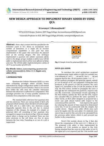
1.INTRODUCTION Quantum-dot Cellular Automata (QCA) is a new nano computing paradigm which encodes binary information by charge configuration within a cell instead of the conventional current switches. There is no current flow within the cells since the columbic interaction between the electrons is sufficient for computation. This paradigm provides one of many possible solutions for transistor-less computation at the nano scale. The standard QCA cells have four quantum dots and two electrons. There are various kinds of QCA cells proposed which include a four-dot QCA cell and an eightdot QCA cell. In a QCA Cell-l, two electrons occupy diagonally opposite dots in the cell due to mutual repulsion of like charges. An example of a simple un polarized QCA cell consisting of four quantum dots arranged in a square is as shown in Fig.1. Dots are simply places where a charge can be localized. There are two extra electrons in the cell those are free to move between the four dots. Tunneling in or out of a cell is suppressed.
© 2016, IRJET
Fig -1: Simple 4-dot Un polarized QCA cell. NOVEL QCA ADDER To introduce the novel architecture proposed for implementing ripple adders in QCA, let consider two n-bit addends A = an−1, . . . , a0 and B = bn−1, . . . , b0 and suppose that for the i th bit position (with i = n − 1, . . . , 0) the auxiliary propagate and generate signals, namely pi = ai+ bi and gi= ai· bi , are computed. Ci being the carry produced at the generic (i−1)th bit position, the carry signal ci+2, furnished at the (i+1)th bit position. In this way, the RCA action, needed to propagate the carry ci through the two subsequent bit positions, requires only one MG. Conversely, conventional circuits operating in the RCA fashion, namely the RCA and the CFA, require two cascaded MGs to perform the same operation. In other words, an RCA adder designed as proposed has a worst case path almost halved with respect to the conventional RCA and CFA. CLA improve the speed by reducing the amount of time required to determined carry bits. It can be constructed with the simpler, but usually slower. Ripple carry adder (RCA) since each carry bit ripples into the next adder. it's relatively slow since it has to wait for the carry bit to be calculated from the previous adder before which it can't proceed any further in the computation. Novel 2-bit module shown in Fig. 2 that also shows the computation of the carry ci+1 = M(pi gi ci ). The proposed n-bit adder is then implemented by cascading n/2 2-bit modules as shown in Fig. 2(a). Having assumed that the carry-in of the adder is cin= 0, the signal p0 is not required and the 2-bit module used
ISO 9001:2008 Certified Journal
Page 248