International Research Journal of Engineering and Technology (IRJET) Volume: 03 Issue: 01 | Jan-2016
www.irjet.net
e-ISSN: 2395 -0056 p-ISSN: 2395-0072
Design, Analysis and Testing of shaft mounted speed reducer for coil winding machine. Kate-Deshmukh N.S.1, Gaikwad M.U.2 1
PG Student, Mechanical Engineering Department, DGI FOI, Maharashtra, India Professor, Mechanical Engineering Department, DGI FOI, Maharashtra, India
2 Asst.
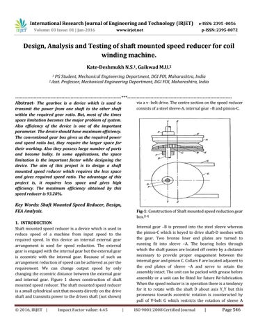
---------------------------------------------------------------------***-------------------------------------------------------------------via a v -belt drive. The centre section on the speed reducer Abstract- The gearbox is a device which is used to consists of a steel sleeve-A, internal gear –B and pinion-C.
transmit the power from one shaft to the other shaft within the required gear ratio. But, most of the times space limitation becomes the major problem of system. Also efficiency of the device is one of the important parameter. The device should have maximum efficiency. The conventional gear box gives us the required power and speed ratio but, they require the larger space for their working. Also they possess large number of parts and become bulky. In some applications, the space limitation is the important factor while designing the device. The aim of this project is to design a shaft mounted speed reducer which requires the less space and gives required speed ratio. The advantage of this project is, it requires less space and gives high efficiency. The maximum efficiency obtained by this speed reducer is 93.28%.
Key Words: Shaft Mounted Speed Reducer, Design, FEA Analysis.
Fig-1: Construction of Shaft mounted speed reduction gear box.[14]
1. INTRODUCTION Shaft mounted speed reducer is a device which is used to reduce speed of a machine from input speed to the required speed. In this device an internal external gear arrangement is used for speed reduction. The external gear is engaged with the internal gear but the external gear is eccentric with the internal gear. Because of such an arrangement reduction of speed can be achieved as per the requirement. We can change output speed by only changing the eccentric distance between the external gear and internal gear. Figure 1 shows construction of shaft mounted speed reducer. The shaft mounted speed reducer is a small cylindrical unit that mounts directly on the drive shaft and transmits power to the driven shaft (not shown) © 2016, IRJET |
Impact Factor value: 4.45
Internal gear –B is pressed into the steel sleeve whereas the pinion-C which is keyed to drive shaft-D meshes with the gear. Two bronze liner end plates are turned to running fit into sleeve –A. The bearing holes through which the shaft passes are located off centre by a distance necessary to provide proper engagement between the internal gear and pinion C. Collars F are located adjacent to the end plates of sleeve –A and serve to retain the assembly intact. The unit can be packed with grease before assembly or a unit can be fitted for future Re-lubrication. When the speed reducer is in operation there is a tendency for it to rotate with the shaft D about axis Y_Y but this proneness towards eccentric rotation is counteracted by pull of V-belt G which restricts the rotation of sleeve A |
ISO 9001:2008 Certified Journal
|
Page 546