International Research Journal of Engineering and Technology (IRJET)
e-ISSN: 2395-0056
Volume: 03 Issue: 01 | Jan-2016
p-ISSN: 2395-0072
www.irjet.net
COMPUTER AIDED DESIGN OF BROADBAND MODIFIED CIRCULAR MICROSTRIP PATCH ANTENNA. Mr. V.M.Patil1, Mr.Prof. R.M.Khaire 2 Electronics Dept.Bharati vidyapeeth’s collage of Engg.pune-43 ,Maharashtra, India. & professor, E & TC Dept.Bharati vidyapeeth’s collage of Engg.pune-43 ,Maharashtra, India.
1 2HOD
---------------------------------------------------------------------***--------------------------------------------------------------------Key Words: VSWR, RETURN LOSS, BANDWIDTH, HFSS, MICRO STRIP PATCH, RADIATION PATTERN, SMITH CHART.
INTRODUCTION An antenna is defined as a transducer that transmits and receives transmits electromagnetic waves. so antenna is referred as directional also probing device. For space borne application the primarily and popularly used antennas are the Micro strip patch antennas. The Micro strip patch antennas have many features, these features makes the microstrip patch antennas popularly used in space applications.
ANTENNA FEED NETWORK For the feeding of Microstrip patch antenna there is variety of methods. Mainly these methods are classified into two categories –
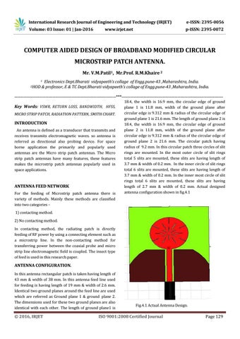
18.4, the width is 16.9 mm, the circular edge of ground plane 1 is 11.8 mm, width of the ground plane after circular edge is 9.312 mm & radius of the circular edge of ground plane 1 is 21.6 mm. The length of ground plane 2 is 18.4, the width is 16.9 mm, the circular edge of ground plane 2 is 11.8 mm, width of the ground plane after circular edge is 9.312 mm & radius of the circular edge of ground plane 2 is 21.6 mm. The circular patch having radius of 9.2 mm. In this circular patch three circles of slit rings are mounted. In the most outer circle of slit rings total 5 slits are mounted, these slits are having length of 3.7 mm & width of 0.2 mm. In the inner circle of slit rings total 6 slits are mounted, these slits are having length of 3.7 mm & width of 0.2 mm. In the inner most circle of slit rings total 6 slits are mounted, these slits are having length of 2.7 mm & width of 0.2 mm. Actual designed antenna configuration shown in fig.4.1
1) contacting method. 2) No contacting method. In contacting method, the radiating patch is directly feeding of RF power by using a connecting element such as a microstrip line. In the non-contacting method for transferring power between the coaxial probe and micro strip line electromagnetic field is coupled. The insect type of feed is used in this research paper.
ANTENNA CONFIGURATION. In this antenna rectangular patch is taken having length of 43 mm & width of 38 mm. In this antenna feed line used for feeding is having length of 19 mm & width of 2.6 mm. Identical two ground planes around the feed line are used which are referred as Ground plane 1 & ground plane 2. The dimensions used for these two ground planes are also identical with each other. The length of ground plane1 is
© 2016, IRJET
Fig.4.1 Actual Antenna Design.
ISO 9001:2008 Certified Journal
Page 129