International Research Journal of Engineering and Technology (IRJET)
e-ISSN: 2395 -0056
Volume: 03 Issue: 12 | Dec -2016
p-ISSN: 2395-0072
www.irjet.net
Design and Working of Adjustable Manually Push Operated Pesticide Spraying Machine Mr. Akhilesh K. Bhatkar1, Dr.P.B.Khope2, Prof. P. S. Chaudhari 3 1Student, Dept. of Mechanical Engineering, Priyadarshini College of Engineering, Nagpur, Maharashtra, India
akhileshbhatkar@gmail.com
2Assistant Professor, Dept. of Mechanical Engineering, Priyadarshini College of Engineering, Nagpur, Maharashtra,
India, khopepb@yahoo.co.in
3Assistant Professor, Dept. of Mechanical Engineering, Priyadarshini College of Engineering, Nagpur, Maharashtra,
India, pschaudharipatil@gmail.com ---------------------------------------------------------------------***---------------------------------------------------------------------
Abstract - Agriculture has been the backbone of Indian
We have seen above drawbacks and limitations of traditional as well as advanced sprayers. So there is a need of time to develop such a pesticide spraying machine which removes or decreases the limitations of above all sprayers. So this project is going to be manually push operated adjustable, efficient, and time saving, pain relieving.
economy. But advancement and mechanization of agricultural tools is slow as compared to other sectors. There are many areas in agricultural sector where speed of modernization is quiet slow. One of the main sectors is pesticide spraying machine. By modernization in this sector pesticides can be evenly distributed on farms which will reduce wastage of pesticide and hence prevents wastage of inputs applied on farms which reduces cost of production. One such machine is developed in which height of sprayers, horizontal adjustments of nozzles and self-adjusting power driven mechanism is developed. This mechanism is free of fuel and its operation is easy and painless. This is first four wheeled pesticide sprayer is developed as a step towards modern farming.
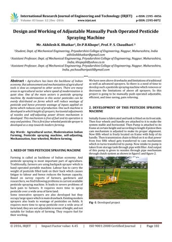
2. DEVELOPMENT OF THIS PESTICIDE SPRAYING MACHINE Initially frame is fabricated and tank is fitted on its front side. Then four wheels and handle are attached to it to make the system stable and horizontal. Then Pump is attached to its frame at certain height and according to length if piston then cam mechanism is adjusted to make its proper alignment. Now fifth wheel is freely located on frame with help of its handle. Then transmission chain is fitted on it so that power from free fifth wheel gets transferred to cam mechanism which in turns transferred to pump. Now intake to pump is taken from storage tank through pipe with filter. And output of this pump is given to nozzles through pipe mechanism through clutch system as shown in figure1 and figure 2.
Key Words: Agricultural sector, Modernization Indian Farming, Pesticide spraying machine, self-adjusting, Mechanization, four wheeled, Modern farming.
1. NEED OF THIS PESTICIDE SPRAYING MACHINE Farming is called as backbone of Indian economy. And pesticide spraying is most important part of agriculture. Traditionally, farmers are using backpack sprayer which is hand operated portable machine. Labour has to carry the weight of pesticide filled tank on their back which causes fatigue to labour and hence reduces the human capacity. Based on survey reports of farmers, gardeners and researchers, we find following problems in current available pesticide spraying machine. It leads to severe problems of back pain to farmers. It requires more time to spray pesticide over a wide area of farm land. Some innovative sprayers are also developed but they occupy large space which is main drawback. Existing modern sprayers also leads to wastage of pesticides on fields. It requires more time to spray pesticide over a wide area of farm land; they are not adjustable in sense of height, and not suitable for Indian style of farming. They require fuel for their working.
© 2016, IRJET
|
Impact Factor value: 4.45
Fig -1: Developed project
|
ISO 9001:2008 Certified Journal
|
Page 102
International Research Journal of Engineering and Technology (IRJET)
e-ISSN: 2395 -0056
Volume: 03 Issue: 12 | Dec -2016
p-ISSN: 2395-0072
www.irjet.net
force for machine in order to check whether drive force required to push the machine is in permissible limit of an average human pushing force according to ergonomics. This can be explained as follows. For calculation of demand drive force/ Total tractive force (TTE) of machine it is important to calculate a) force required to overcome rolling resistance of whole machine (RR), b) force to overcome gradient resistance of machine (GR), c) force to accelerate equipment to gain its maximum velocity for operation (FA), d) force to overcome resistance due to power generating fifth wheel (FB).
Fig -2: CAD model of project
3. WORKING OF THIS PESTICIDE SPRAYING MACHINE
TTE [Kg] = RR [Kg] + GR [Kg] + FA [Kg] + FB [Kg]…………………………….. (A)
Working of this model can be explained with help of figure 3.
a) Estimation of rolling resistance (RR) RR [Kg] = GVW [Kg] x Crr [-] Where: RR = rolling resistance [Kg] GVW = gross vehicle weight [Kg] Crr = surface friction
When person will push this machine through handle (1) then the whole machine will move in forward direction using four wheels (2) As the machine moves in forward direction, fifth free toothed wheel will also move with the machine. As this toothed wheel (3) will move the tooth’s on it will engage with land and hence will create power on it. This rotation of wheel transfer this power to reciprocating pump (7) through two chain drives (4) and (5) and then through cam mechanism (6). As toothed wheel will rotate two chain drives will rotate which will rotate cam mechanism which generates reciprocating motion to piston of pump. As pump works it will suck water pesticide mixture from storage tank (8) through pipes (9) and this will pressurize in pump. When needed this pesticide is passed through Flat Pan Nozzles attached to boom (10). Height of this boom with nozzle can be adjusted by adjusting height of boom on boom support (11).
Fig -4: Table for surface friction between rubber wheels and contact surface So, RR [Kg] = GVW [Kg] x Crr [-] = 70 x 0.09 Crr = Considering Medium Mud RR [Kg] = 6.3 Kg……… (1) a) Estimation of grade resistance (GR) GR [Kg] = GVW [Kg] x sin (α) Where:
Fig -3: CAD model description
GR = grade resistance [Kg]
4. DESIGN OF DRIVING MECHANISM FOR THIS PESTICIDE SPRAYING MACHINE
GVW = gross vehicle weight [Kg]
Important design parameter in this project is design of driving mechanism. This design includes estimation of drive
© 2016, IRJET
|
Impact Factor value: 4.45
|
ISO 9001:2008 Certified Journal
|
Page 103
International Research Journal of Engineering and Technology (IRJET)
e-ISSN: 2395 -0056
Volume: 03 Issue: 12 | Dec -2016
p-ISSN: 2395-0072
www.irjet.net
α = maximum incline angle [degrees]= 10 degree (consideration)
Force (Fa) on piston is nothing but force on piston rod Di. We know that force acting on piston rod is Fa = ( ) x xP
So,
=( )x
GR [Kg] = GVW [Kg] x sin (α)
x 0.25
= 283.52 N or 28.3 Kg……… (i)
= 70 x sin (10) GR [Kg] = 12.15 Kg……… (2)
II) To calculate force due to Piston cylinder assembly including friction losses in piston:
b) Estimation of acceleration force (FA) FA [Kg] = GVW [Kg] x Vmax [m/s] / 9.8 [m/ ] x ta [s]
Consider total 1 percent of friction losses are there in piston cylinder assembly.
Where:
So these 1 percent friction losses are
FA = acceleration force [Kg]
= Total force in piston assembly x 1 percent loss
GVW = gross vehicle weight [Kg]
= 28.3 x 0.01
Vmax = maximum speed [m/s]
= 0.283 kg force will resist the action of piston.
ta = time required to achieve maximum speed [s] Consider maximum velocity the machine achieved is 10m/s in 10 seconds. So, FA [Kg] = GVW [Kg] x Vmax [m/s] / 9.8 [m/
] x ta [s]
=70 x 0.1666 / 9.8 x 10 FA [Kg] = 0.119 Kg……… (3) c) Estimation of force on toothed wheel (FB) Toothed wheel is used to drive piston cylinder arrangement via transmission to generate pressure of 2.5 kg/ N/
Fig -5: Table of standard transmission losses considered in industries
or 0.25
maximum pressure (P) (as calculated below). So the
So total force acting due to piston cylinder assembly is
opposing force acting on human is to overcome forces acting
Fb = Total force action on piston (Fa) + Force due to friction in assembly
on fifth wheel which is nothing but forces exerting on it from piston to the fifth wheel.
= 28.3 + 0.283
Force generating on fifth wheel is pressure force which is in
Fb = 28.583 Kg……… (ii)
compression state on piston to fifth wheel via cam
III) To calculate force due to transmission losses due to cam mechanism.
mechanism and two chain transmissions.
Further losses added due to cam mechanism is nothing but cam transmission force loss added to total force on piston assembly. From table 4.2 as above total transmission loss considered due to cam mechanism is 5 percent.
To calculate force on wheel we have to calculate i) Force on piston ii) transmission losses in Cam mechanism and iii) Losses in two chain drives. I) to calculate force on piston:
© 2016, IRJET
|
Impact Factor value: 4.45
So total force Fc acting including transmission losses due to cam mechanism is
|
ISO 9001:2008 Certified Journal
|
Page 104
International Research Journal of Engineering and Technology (IRJET)
e-ISSN: 2395 -0056
Volume: 03 Issue: 12 | Dec -2016
p-ISSN: 2395-0072
www.irjet.net
Now according to Waldevar Kanwowski and William S. Marros in e-book “The Occupational Ergonomics Handbook” an average person can exert a maximum pushing force of 640 N.
Fc= Fb + Transmission losses due to cam mechanism = Fb + (Fb x 5%) = Fb + (Fb x
)
= 28.583 + (28.583 x
And according to our calculation total pushing force considering all factors is calculated as 488.33N.
)
As 488.33N < 640N
Fc =30.00 kg……… (iii)
So, an average person can exert a maximum pushing force > Total pushing force for this machine.
IV) To calculate force due to transmission losses due to two chain drives.
So our machine is easily functional considering all ergonomic factors. So our design is safe.
So total force Fd acting due first chain drive mechanism transmission losses is
5.
Fd= Fc + Transmission losses due to cam mechanism
= 30.00 + (30.00 x
)
Fd =30.60 kg……… (iv)
3) Machine takes around 7 hours to complete spraying of 1 hector of land,
So total force Fe acting due first chain drive mechanism transmission losses is
4) And it sprays mixture of around 242 liters pesticidewater uniformly to cover 1 hector of land,
Fe= Fd + Transmission losses due first chain drive mechanism
5) 12 times refilling of mixture is needed to cover 1 hector of land and it takes 35 minutes to empty 1 full tank of pesticide mixture,
= Fd + (Fd x 2%) )
= 30.60 + (30.60 x
6) According to structure of land it has self-adjustable 5th power driving wheel,
)
7) End to end wheel base of project is adjustable in range of 14-16 inches,
Fe =31.21 kg……… (v) So total force acting due to fifth wheel assembly including all transmission losses is given by
8) Well balanced and hazard free machine, 9) No fuel requirement,
FB [Kg] = 31.21 Kg……… (4)
10) Capacity of tank can be adjusted from 20-40 liters and hence performance can be increased.
So, Total Tractive force TTE is TTE [Kg] = RR [Kg] + GR [Kg] + FA [Kg] + FB [Kg]
CONCLUSION
= 6.3 + 12.15 + 0.119 + 31.21
It is found that the existing pesticide spraying machines use petrol and diesel to run. It can cause pollution and further the vibration produced in the machine cause noise pollution, while portable hand held machine may cause health problems for person as he directly comes in contact with insecticide. In advent of avoiding such problems enlisted in first point, an adjustable manually push operated pesticide
TTE [Kg] = 49.77 Kg = 49.77 x 9.81 N TTE [N] = 488.33 N
© 2016, IRJET
ASPECTS
1) This machine sprays and cover area of 10 feet horizontally and 6 feet vertically and can be adjusted in this range, 2) Nozzles can also be adjusted according to pattern of crops,
)
= Fd + (Fd x
IMPORTANT
DEVELOPED IN THIS PROJECT
= Fc + (Fc x 2%) = Fc + (Fc x
HIGHLIGHTED
|
Impact Factor value: 4.45
|
ISO 9001:2008 Certified Journal
|
Page 105
International Research Journal of Engineering and Technology (IRJET)
e-ISSN: 2395 -0056
Volume: 03 Issue: 12 | Dec -2016
p-ISSN: 2395-0072
www.irjet.net
spraying pump seems an alternative concept. Comparison between the existing machineries and present machine shows that an adjustable manually push operated pesticide spraying pump can work very efficiently with respect to covering area, time and cost of spraying process. Also it seems economical. The demand force required for spraying shows that this machine can be used efficiently in all types of farms. This machine is adjustable in height as well as it area of spraying can be adjusted depending on pattern of plants which makes this machine unique in nature. Since human energy is needed to drive the machine, it may provide jobs to the persons for uneducated person who is need for such jobs.
[9] Prof. Swapnil L. Kolhe, Nilesh B. Gajbhiye, “Eco-friendly Mechanically
Operated
Multipurpose
Spray
Pump”.
International Journal of Research in Advent Technology, Vol.2, No.2, February 2014 E-ISSN: 2321-9637 [10] Third National Technological Innovations And Traditional Knowledge Awards Page 171-180. [11] Krushi Sutra – Profiles of Agricultural Innovations In India [12] Shivaraja kumar. A, Parameswaramurthy. D, “Design and Development of Wheel and Pedal Operated Pump”. IPASJ
REFERENCES:
International Journal of Mechanical Engineering (IIJME) Volume 2, Issue 6, June 2014 ISSN 2321-6441
1] Pesticide Application Techniques. [2] Sprayers and Their Functions, Classifications, Manually
WEBSITES:
Operated Sprayers, Power Sprayers- Dusters, Types and 1.
Uses Sprayers.
http://www2.mae.ufl.edu/designlab/motors/EML2
[3] Nitin Das, Namit Maske, Vinayak Khawas, “Agriculture
322L%20Drive%20Wheel%20Motor%20Torque%
Fertilizers and Pesticide Sprayers – A Review”. IJIRST –
20Calculations.pdf
International Journal for Innovative Research in Science &
2.
Technology| Volume 1 | Issue 11 | April 2015 ISSN (online):
http://www.womackmachine.com/pdf/rb365/47th /section10/sec10pg504pumpmotortransmissioneff
2349-6010
iciencies.pdf
[4] Mahesh H.R, Kiran Kumar, Siddhesh K.B, “Multipurpose Push Operated Sprayer”. Project Reference No: 38S1356 [5] P.D.P.R.Harsh Vardhan, S.Dheepak, P.T.Aditya, Sanjivi Arul, “Development of Automated Aerial Pesticide Sprayer”. IJRET: International Journal of Research in Engineering and Technology eISSN: 2319-1163 | pISSN: 2321-7308 [6] Mahesh M. Bhalerao, Azfar M. Khan, Dattu T. Unde, “Development and Fabrication of Smart Spray Pump”. Shivajirao S. Jondhale College of Engineering, Dombivli (E), Mumbai University [7] Sandeep H. Poratkar, Dhanraj R. Raut, “Development of Multinozzle Pesticide Sprayer Pump”. International Journal of Modern Engineering Research (IJMER) Vol.3, Issue.2, MarchApril. 2013 pp-864-868 ISSN: 2249-6645 [8] Herbert H. Tackett, James A. Cripe, “Positive Displacement Reciprocating Pump Fundamentals- Power and Direct Acting Types”. Proceedings of The Twenty Fourth International Pump Users Symposium- 2008
© 2016, IRJET
|
Impact Factor value: 4.45
|
ISO 9001:2008 Certified Journal
|
Page 106