International Research Journal of Engineering and Technology (IRJET)
e-ISSN: 2395 -0056
Volume: 03 Issue: 11 | Nov -2016
p-ISSN: 2395 -0072
www.irjet.net
COMPARISON OF CO-CENTRIC BRACING SYSTEM SUBJECTED TO WIND LOADING 1Gayatri Thakre, 2Dr. A.A. Bage 1student,civil department , Sardar Patel College of Engineering, Maharashtra India
2HOD, structural department, Sardar Patel College of Engineering, Maharashtra India
---------------------------------------------------------------------***---------------------------------------------------------------------
Abstract – Any structure is made to resist different types of
loading. The loads like dead load and live load acts vertically downward direction and hence helps to stabilize the structure, where as the structure is not only subjected to vertical forces but they may also be subjected to horizontal forces due to Earthquake, wind load, etc. Due to this horizontal forces structure is manly subjected to overturning or twisting. These horizontal forces are dynamic in nature. To resist this horizontal forces bracing plays vital role in case of steel structure. In current paper, analysis on effect of wind load on steel structure is evaluated. For evaluation different types of bracing systems are compared on basis of story displacement, story drift, base shear and force in bracing members.
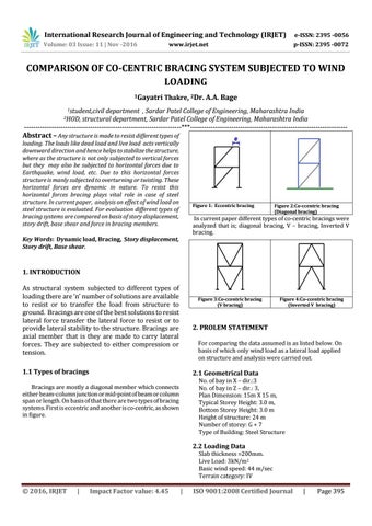
Figure 1: Eccentric bracing
Figure 2:Co-ccentric bracing (Diagonal bracing)
In current paper different types of co-centric bracings were analyzed that is; diagonal bracing, V – bracing, Inverted V bracing.
Key Words: Dynamic load, Bracing, Story displacement, Story drift, Base shear.
1. INTRODUCTION As structural system subjected to different types of loading there are ‘n’ number of solutions are available to resist or to transfer the load from structure to ground. Bracings are one of the best solutions to resist lateral force transfer the lateral force to resist or to provide lateral stability to the structure. Bracings are axial member that is they are made to carry lateral forces. They are subjected to either compression or tension.
Figure 3:Co-ccentric bracing (V bracing)
Figure 4:Co-ccentric bracing (Inverted V bracing)
2. PROLEM STATEMENT For comparing the data assumed is as listed below. On basis of which only wind load as a lateral load applied on structure and analysis were carried out.
1.1 Types of bracings
2.1 Geometrical Data No. of bay in X – dir.:3 No. of bay in Z – dir.: 3, Plan Dimension: 15m X 15 m, Typical Storey Height: 3.0 m, Bottom Storey Height: 3.0 m Height of structure: 24 m Number of storey: G + 7 Type of Building: Steel Structure
Bracings are mostly a diagonal member which connects either beam-column junction or mid-point of beam or column span or length. On basis of that there are two types of bracing systems. First is eccentric and another is co-centric, as shown in figure.
2.2 Loading Data Slab thickness =200mm. Live Load: 3kN/m2 Basic wind speed: 44 m/sec Terrain category: IV
© 2016, IRJET
|
Impact Factor value: 4.45
|
ISO 9001:2008 Certified Journal
|
Page 395
International Research Journal of Engineering and Technology (IRJET)
e-ISSN: 2395 -0056
Volume: 03 Issue: 11 | Nov -2016
p-ISSN: 2395 -0072
www.irjet.net
Class: B Location: Mumbai Life of Structure: 50 years Plain Terrain Load combinations: 1.2DL+1.2LL+1.2WL Member Size - 200 mm * 200mm
3. LOAD CALCULATION
A. Dead Load calculations Density of concrete =25kN/m3 Hence, self-weight of Slab = 5 kN/m2 Dead load on the outer beam =8.33 kN/m Dead load on the inner beam=2 * 8.33=16.67 kN/m B. Live load calculations Since live load = 3 kN/m2 Live load on the outer beam=5 kN/m Live load on the inner beam=5*2=10 kN/m C. Wind load calculationFrom IS 875(part 3)-1987 k2 at 18m=0.76 k2 at 21m=0.777 k2 at 24m=0.828 Using Vz=k1* k2 * k3 * Vb Where, Vz=design wind speed at any height z in m/s k1= probability factor(risk coefficient) =1.0 k2= terrain, height and structure size factor and k3= topography factor =1.0 Vb= basic wind speed in m/s Therefore, Vz at 18m=33.44 m/s Vz at 21m=34.188 m/s Vz at 24m=36.432 m/s Using Pz= 0.6 * Vz2 Where, Pz= design wind pressure in N/m2 Pz at 18m = 0.6709 kN/m2 Pz at 21m = 0.7013 kN/m2 Pz at 24m= 0.7937 kN/m2
Figure 6 : Front view of Un-braced frame
Figure 7 : Front view of Diagonal brace frame
4. MODELS IN STAAD Pro.
Figure 8 : Front view of V- brace frame
Figure 5 Plan view
© 2016, IRJET
|
Impact Factor value: 4.45
|
ISO 9001:2008 Certified Journal
|
Page 396
International Research Journal of Engineering and Technology (IRJET)
e-ISSN: 2395 -0056
Volume: 03 Issue: 11 | Nov -2016
p-ISSN: 2395 -0072
www.irjet.net
Unbraced farme 22.021
Base Shear (kN) V Diagonal Bracin Bracing g 116.505 57.694
Inverted V Bracing 59.547
Figure 9 : Front view of Inverted V- brace frame
5. RESULTS AND GRAPHS Story Displacement (mm) Unb Hei race Diagonal Inverted V ght d V Bracing Bracing Bracing (m) farm e 24 20 4 4 2 21 19 4 3 2 18 18 3 3 1 15 16 3 3 1 12 13 2 2 1 9 10 2 2 1 6 7 2 1 0 3 3 1 1 0 0 0 0 0 0
Graph 2: Base Shear
Unbraced farme 38.004
Base Moment (kNm) V Diagonal Bracin Bracing g 11.288
Inverted V Bracing
11.137
10.032
Graph 3: Base Moment Max. Axial Force in brace member (kN) V Unbraced Diagonal Inverted V Bracin farme Bracing Bracing g -133.954 88.137 92.392
Graph 1: Story displacement
© 2016, IRJET
|
Impact Factor value: 4.45
|
ISO 9001:2008 Certified Journal
|
Page 397
International Research Journal of Engineering and Technology (IRJET)
e-ISSN: 2395 -0056
Volume: 03 Issue: 11 | Nov -2016
p-ISSN: 2395 -0072
www.irjet.net
Bracing System(A Software Approach)”,in International Journal of Innovative Research in Science,Engineering and Technology, New Delhi, India, 2013. [4] Sourabh R. Dinde and Rajshekar S. Talikoti, “Structural Behaviour of Industrial Pallet Rack with Braced and Unbraced Frames” in International Journal of Current Engineering and Technology, Maharashtra, India, 2015. [5] M. Mohana Ram,“Comparisons of the Different Bracing Systemwith Lateral and Transverse Loading on 2D SteelFrame” in International Journal of Engineering Research & Technology, Virudhinagar, India, 2016. [6] Nathalie Robert and Robert Tremblay, “Seismic Design And Behavior of Chevron Steel Braced Frames” in WCEE, India, 2000.
Graph 4: Base Moment Story Drift (mm) Heigh t (m)
Unbrace d farme
Diagonal Bracing
V Braci ng
Inverted V Bracing
24 21 18 15 12 9 6 3 0
1 1 2 3 3 3 4 3 0
0 1 0 0 0 1 0 0 0
1 0 0 1 0 1 0 1 0
0 1 0 0 0 1 0 0 0
6. CONCLUSIONS 1. Displacement due to wind loading were effectively resisted by bracing in which inverted v bracing were reduce more displacement than other type of bracings. 2. Due to bracing horizontal shear force at base of footing increases and base moment reduces. 3. Axial force in diagonal bracing is more as compare to other type of bracings. 4. Due to bracing indeterminacy of the structure increases also base shear is increases. On other side structure gets stiffer to resist horizontal displacement.
REFERENCES IS 875(part 3) 1987- Indian Standards- Code of practice for design loads (other than earthquake) for buildings and structures. Part 3-wind loads (second revision). [2] Suresh P et al.,” Influence of diagonal braces in RCC multi-storied frames under wind loads: A case study” in International Journal of Civil And Structural Engineering, Andhra Pradesh,India 2012. [3] Nauman Mohammed and Islam Nazrul,“ Behaviour of Multistorey RCC Structure with Different Type of [1]
© 2016, IRJET
|
Impact Factor value: 4.45
|
ISO 9001:2008 Certified Journal
|
Page 398