International Research Journal of Engineering and Technology (IRJET)
e-ISSN: 2395-0056
Volume: 03 Issue: 01 | Jan-2016
p-ISSN: 2395-0072
www.irjet.net
MODELING AND STRESS ANALYSIS OF CRANKSHAFT USING FEM PACKAGE ANSYS K.SANDYA1, M KEERTHI2, K.SRINIVAS3 PG Student, Mechanical Engineering, DVR & Dr.HS MIC College of Technology, Andhra Pradesh, INDIA PG Student, Mechanical Engineering, DVR & Dr.HS MIC College of Technology, Andhra Pradesh, INDIA 3 Associate Professor, Mechanical Engineering, DVR & Dr.HS MIC College of Technology, Andhra Pradesh, INDIA 1 2
---------------------------------------------------------------------***--------------------------------------------------------------------Abstract- Crankshaft is one of the critical components for the effective and precise working of the internal combustion engine. It has a complex shape of geometry. In an arbitrary position of the crank, due to tangential force, the crank arm will be subjected to transverse shear, bending and twisting, while due to radial component it is subjected to direct stress and bending. It will be laborious to consider all these straining actions in several positions of the crank. Generally, the crank is designed for two positions; those are maximum twisting moment and maximum bending moment.In this project, an attempt has been made to analyze the crankshaft in several positions of the crank, by using Finite element software ANSYS. The static analysis is conducted on the crankshaft with three different materials in different orientations. The results are validated with theoretical calculations for two crank positions for all materials.
Key Words:Crankshaft, Solidworks, hypermesh, ANSYS Workbench, FEM, Al6061, Inconel x750 There are many sources of failure in the engine one of the most common crankshaft failure is fatigue at the fillet areas due to the bending load causes by the combustion. At the moment of combustion the load from the piston is transmitted to the crankpin, causing a large bending moment on the entire geometry of the crankshaft. At the root of the fillet areas stress concentrations exist and these high stress range locations are the points where cyclic loads could cause fatigue crank initiation leading to fracture.
1. INTRODUCTION The crankshaft plays a vital role in all Internal Combustion Engines. It is a large component, which converts the reciprocating displacement of the piston into rotary motion with a four link mechanism. It has complex shape of geometry. The crankshaft experiences a cyclic load, due to the cyclic load fatigue failure occur over a period. The fatigue analysis has to be considered in the design stage itself. The design and development of crankshaft is always been an important task for the production industry, in order to reduce the manufacturing cost of the product, minimum weight possible and proper fatigue strength and other functional requirements. These improvements result in lighter and smaller engines with better fuel efficiency and higher power output. This study was conducted on a four cylinder four stroke cycle engine. Three different crankshafts from similar engines were studied in this research. The finite element analysis was performed for each crankshaft.Crankshaft must be strong enough to take the downward force of the power stroke without excessive bending so the reliability and life of the internal combustion engine depend on the strength of the crankshaft largely. The crank pin is like a built in beam with a distributed load along its length that varies with crank positions. Each web is like a cantilever beam subjected to bending and twisting.
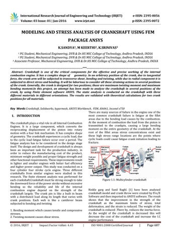
Figure 1.1: Multicylinder crankshaft Rinkle garg and Sunil Baghl. [1] have been analyzed crankshaft model and crank throw were created by Pro/E Software and then imported to ANSYS software. The result shows that the improvement in the strength of the crankshaft as the maximum limits of stress, total deformation, and the strain is reduced. The weight of the crankshaft is reduced .There by, reduces the inertia force. As the weight of the crankshaft is decreased this will decrease the cost of the crankshaft and increase the I.C engine performance.
1. Bending moment which causes tensile and compressive stresses. 2. Twisting moment causes shear stress. Š 2016, IRJET |
Impact Factor value: 4.45
|
ISO 9001:2008 Certified Journal
|
Page 687