4 minute read
FEA Analysis of Hydraulic Cylinder using ANSYS

Vishal Yadav1 , Purushottam Sahu 2 , Ghanshyam Dhanera 3
1Research scholar, BM College of Technology, Indore, MP
Advertisement
2Professor and Head Department of mechanical engineering, College of Technology, Indore, MP
3Professor, Department of mechanical engineering, College of Technology, Indore, MP ***
Abstract -A hydraulic cylinder is a mechanical actuator that converts hydraulic energy into linear force and motion. It is a key component in many hydraulic systems used in various industries, such as construction, manufacturing, and transportation. The objective of current research is to investigate the structural characteristics of hydraulic cylinder using techniques of FEA. The modeling of hydraulic cylinder is conducted in designmodelerandstructuralanalysisisconductedusing ANSYS simulation package. The FEA analysis results have shownthatcriticalregionsareobtainedattheendsupport regions.Themidcenterregionofthehydrauliccylinderis almost uniform. The equivalent stress at this region is nearly96.3MPa.Thehydrauliccylinderhassafetyfactorof 1.08whichmakesitfeasiblefortherequiredapplication.
Key Words - FEA, Hydraulic cylinder, Safety factor
1. INTRODUCTION:
Actuators like hydraulic cylinders transform the potential energyofpressurisedfluidintothemechanicalenergyofa rotary motion. An actuator's moving element (piston or plunger) experiences a force that is proportional to the fluid'spressureandthe element'sarea.Figure 1depictsa double-rodhydrauliccylinder.
2. LITERATURE REVIEW
Compositecylinderswithsteellinerswerethesubjectofa technique for designing strength and buckling proposed by Mantovani et al. [6,7]. An actuator with a working pressureof35MPa,aninternaldiameterof300mm,anda stroke of 1960 mm was used in the authors' study. The authors achieved this by adapting a solution to the Lame issue for anisotropic materials. The cylinder's initial strength, together with its circumferential and axial deformation, have been constrained in the design to provideoptimalperformance.
Piston and front cap were made from composite material reinforced with carbon fibre, and FEM analysis was done by Ritchie et al. [8]. The pieces were fabricated from prefabricated pipes using subtractive manufacturing techniques, which are not ideal for use with composites. The composite was deemed to have middling machinability, with poor surface quality and dimensional accuracy being the results. In both corrosion tests and a comparison of their respective weights, the composite materialwasclearlythevictor.
In order to improve tribological conditions at the barrelpistoncontact,ScholzandKroll [9] investigatedremoving thesteellinerfromtheinteriorofthebarrelofahydraulic cylinder and replacing it with a nanocomposite coating. The authors described techniques for nanocomposite coatingproductionandstresscalculationinsideindividual compositelayers.
Front cap (1), piston rod (2), front cap (3), piston (4), barrel(5),rearcap(6),andtailjoint(7)makeuptheparts [2]. Working pressures of up to 25 MPa are typical for standard hydraulic cylinders, with higher-pressure variantsavailableonspecial order.Boththediameterand thepitchmayrangefromafewmillimetres[3,4]toseveral meters[5].
Tocombatthis,KumarandLee[10]createdhybridpiston rods that are made of steel at their core and a composite shell for added strength. Both finite element and experimental testing were conducted on a variety of components ranging in size from 7.5 mm to 30 mm in diameterand650mminlength.Dependingonthekindof construction, the CFRP percentage might be anywhere from 0% (for solid steel rods) to 100% (for all-composite designs). There is evidence that increasing the element's compositecontentimprovesitsbucklingresistance.
3. OBJECTIVE
The objective of current research is to investigate the structural characteristics of hydraulic cylinder using techniques of FEA. The modeling of hydraulic cylinder is conducted in design modeler and structural analysis is conductedusingANSYSsimulationpackage.


4. METHODOLOGY
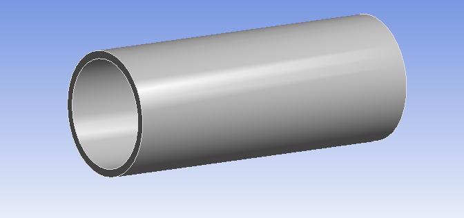
The methodology process involves modeling of piston in design modeler of ANSYS as shown in figure 2. The hydraulic cylinder is modeled using sketch and extrude toolofdesignmodeler.
After applying structural loads on the cylinder, the FEA simulation is run. The FEA simulation process involves formulation of element matrices and global stiffness matrix.
5. RESULTS AND DISCUSSION
Figure2:Designofhydrauliccylinder
Aftermodelingofhydrauliccylinder,themodelischecked for topological consistency and therefore meshed using hexahedral/brick element type as shown in figure 3. The model is meshed with fine relevance and adaptive size function.
From the FEA simulation, the deformation distribution plot and equivalent stress distribution plots are obtained as shown in figure 5 and figure 6 respectively. The maximum deformation is obtained at the center region of the cylinder with magnitude of more .017mm. The deformationis lowerat the corner regionsof the cylinder asshownindarkbluecoloredregion.
Figure3:Meshedmodelofhydrauliccylinder
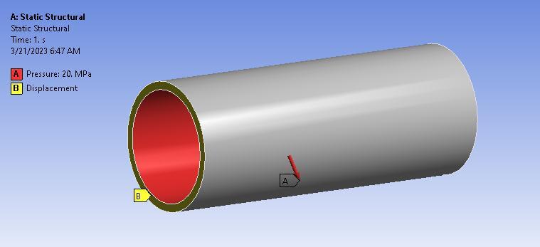
After meshing, the structural loads and boundary conditionsareappliedonthehydrauliccylinderasshown in figure 4. The structural loads and boundary conditions are applied on the hydraulic cylinder which includes applying displacement support at free ends and pressure of20MPaoninnerwallofhydrauliccylinder.
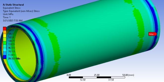
The equivalent stress distribution plot is obtained for cylinder as shown in figure 6. The equivalent stress distribution plot shows higher stresses at the inner surfaces of the cylinder. The stresses on inner surface of thehydrauliccylinderare162MPa.
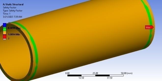
The equivalent stress is lower at the corner regions wherein the stress value is 51.92MPa. The safety factor distributionplotisobtained andminimumsafetyfactoris obtainedattheendregions.
Applications: A Design Procedure. In Proceedings of the International Conference on Mechanical, Automotive and Aerospace Engineering, Kuala Lumpur, Malaysia, 17–19 May2011.
7. Mantovani, S. Feasibility Analysis of a Double-Acting Composite Cylinder in High-Pressure Loading Conditions for Fluid Power Applications. Appl. Sci. 2020, 10, 826. [CrossRef]
8. Ritchie, J.; Mumtahina, U.; Rasul, M.; Sayem, A. Alternative Materials in Hydraulic Cylinder Design Application Of Carbon Fibre Components. Mech. Eng. Res. J.2013,9,43–47.
9. Scholz, S.; Kroll, L. Nanocomposite Glide Surfaces for FRP Hydraulic Cylinders Evaluation and Test. Compos. PartBEng.2014,61,207–213
5. CONCLUSION
The FEA simulation enabled to determine the critical stress regions of hydraulic cylinder. The FEA analysis resultshaveshownthatcriticalregionsareobtainedatthe end support regions. The mid center region of the hydrauliccylinderisalmostuniform.Theequivalentstress at this region is nearly 96.3MPa. The hydraulic cylinder has safety factor of 1.08 which makes it feasible for the requiredapplication.
References
[1] MarekLubecki1 ,MichałStosiak1, “Development of Composite Hydraulic Actuators: A Review” Actuators 2022,11,365.https://doi.org/10.3390/act11120365
2. Li, Y.; Shang, Y.; Wan, X.; Jiao, Z.; Yu, T. Design and Experiment on Light Weight Hydraulic Cylinder Made of Carbon Fiber Reinforced Polymer. Compos.Struct.2022, 291,115564.[CrossRef]
3. Li, N. Multi-Degree-of-Freedom Manipulator Driven by Micro Hydraulic System. In Proceedings of the 2016 7th International Conference on Education, Management, Computer and Medicine (EMCM 2016), Shenyang, China, 29–31December2016;AtlantisPress:Paris,France,2016.
4. Xia, J.; Durfee, W.K. Analysis of Small-Scale Hydraulic Actuation Systems. J. Mech. Des. 2013, 135, 091001. [CrossRef]
5. Truong, V.T.; Hwang, Y.L.; Cheng, J.K.; Tran, K.D. Dynamics Analysis and Numerical Simulation of LargeScale Hydraulic Cylinder Actuators. In Engineering Tribology and Materials IV; Trans Tech Publications Ltd.: Zurich,Switzerland,2020;Volume900,pp.14–19.
6.Mantovani,S.;Costi,D.;Strozzi,A.;Bertocchi,E.;Dolcini, E.DoubleActingCompositeTubeCylinderforFluidPower
10.SP,P.K.;Lee,S.-S.DesignandExperimentalAnalysesof Hybrid Piston Rods Used in Hydraulic Cylinders under AxialLoad.Appl.Sci.2021,11,8552.
