4 minute read
II. ANGLES FOR SUSPENSION GEOMETRY SELECTION


To preserve traction provided by the wheel to the ground and lessen tyre wear, All-terrain vehicles should have some negative camber. To help counteract the improvement in dynamic situation, a modest negative camberisofferedatstatic[3].
Toeinisemployedinstaticpositiontocounteractthe tendency of the tyre to move at odds with one another while accelerating. This has an impact on the car's straight-linestabilityandsteeringreaction.
Advertisement
Toimprovethevehicleself-centeringandtomaintain straight-linemotion,apositivecastorangleismaintained between0and7degrees.
D. Kingpin inclination or KPI
KPI for off-road vehicles should be ranging from 4 to 11degreestobeconsideredideal.Ithasimplicationsfor steering effects and the wheel's vertical movement, which also adds to the self-aligning torque The axis of steering influences the scrub radius value, KPI is thereforegivenamajorvaluetoreducethescrubradius.
III. DESIGN METHODOLOGY:
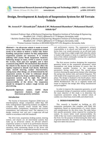
A. LOTUS analysis of geometry
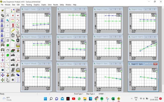
The design is finalized using the Lotus Shark suspension designing software system. The Lotus Shark Suspension Analysis is represented in figure 1. The least amount of anti-dive characteristics is used in the design to keep the ATV stable in all conditions. Before developing the car's suspension, teamconcentrated on a handfulofthemostimportantvehiclecomponents.
Three-dimensional moving models are regularly developed and altered in the LOTUS Shark Suspension Analysis (LSSA). Using LSSA, hard points are drawn Graphical and numerical values are calculated. This modelling strategy makes it simple for users to build their own suspension models. Diagrammatic representations of camber angle and toe angle fluctuations in connection to steering motions including roll, bump, and steering motion are possible. The damping magnitude relationship, sprung and unsprung weight, spring rate, camber angle, caster angle, roll centre, wheelbase, track size, toe angle, and ground clearance are just a few of the variables that should be considered when determining the suspension system's weak points. Therefore, prior to producing, design considerationsmustbemade.
Here, the goal is to reduce any modification to the wheel alignment angle parameters. For effective weight transfer and to reduce tyre wear, reduced track width andwheelbasemodifications[4].Thefinallotusiteration is displayed in accordance with the desired range of suspension angle values and the specified geometric limitations.
B. Geometry of suspension system
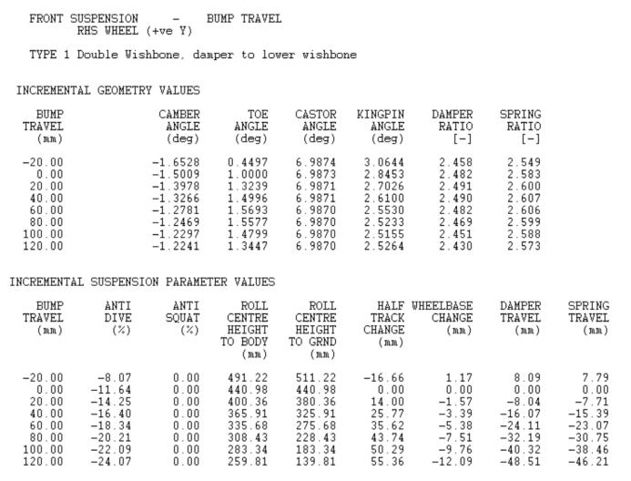
For the front, it is decided to use a double wishbone independent system. The best camber curvature throughout wheel travel is provided bya short longarm arrangement. Negative camber is incorporated onto a shorter upper arm to retain traction during tight turns. Whenever the vehicle is rolling, the inner side wheel droopsanddisplaysafavorablecamberchange,whilethe outer wheel experiences bump and exhibits a negative camber change. Turning radius and bump-steer are two steering metrics that are impacted by the front suspension geometry [5]. To reduce slip angle and understeer risk, the minimum turning radius isachieved [6].

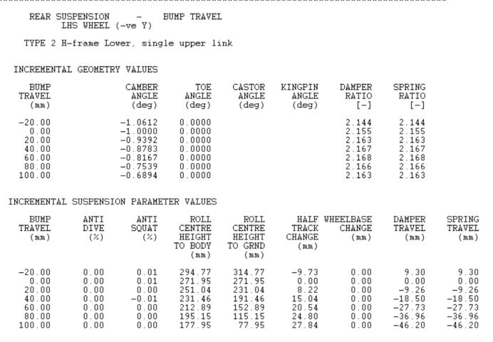
The gearbox system's components are considered while choosing the rear suspension system. By use of a tripodjointthatconnectsthedriveshaft'sinnerendtothe gearbox, the wheel travel is constrained due to the driveshaft's limited range of motion. In the back, a suspensionsystemwithasingleupperlinkandanH-Arm wishbone. It exhibits toe-in and toe-out tendencies because the back wheel does not have steering, which may lead to oversteer or understeer, respectively [7]. Thiscouldleadtoanimbalanceand,ultimately,a loss of control. Because of this, H-arm is utilized instead of Aarm.TheH-armconfigurationincreasesridestabilityand assuresaccuratealignmentindynamiccircumstances.
Bump steer
When the road is bumpy and the car is moving, the toe angle changes. Because of the undesired wheel motion, it is minimized. Understeer and oversteer characteristics are also impacted by bump steer [4]. When there is a bump, a wheel with toe out tends to understeer, whereas a wheel with toe in tends to oversteer[9].Inordertopreventexcessivetyrewear,the tyres must be realigned when the ATV hits bumps or droop. The least amount of bump steer is ideal for a desired performance. As a result, the toe change is zero becausetheICpointislocatedonthesameaxisasthetie rodpoints.
Roll center height
One of the crucial parameters, roll centre height, typicallyrequiresseveralcyclesbeforereachingtheideal value.Duetotheassembly'strackwidthconstraints,itis impossible to iterate the lower wishbone suspension positions.However,byalteringtheICpointanditerating the upper wishbone coordinates, it is possible to change the roll centre height. To boost the vehicle's stability whileaccountingforthe60:40bias(ReartoForward), It isidealfortherollaxisslopeangletobearound1degree.
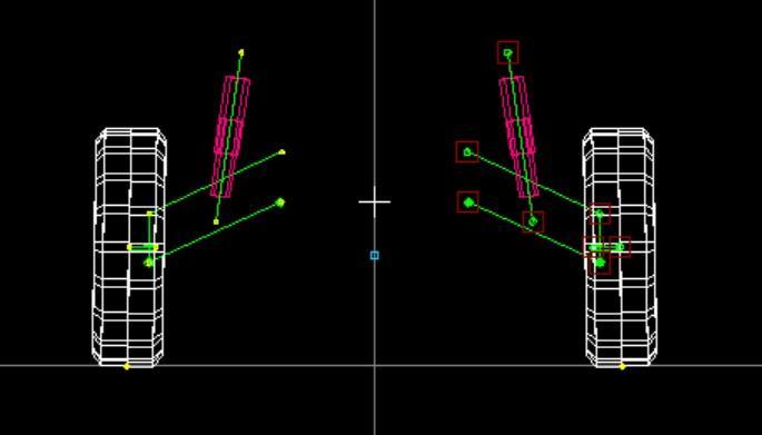
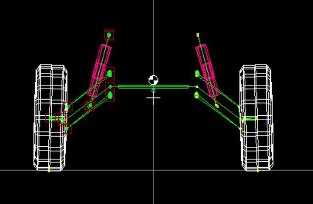
IV.MULTIBODY DYNAMICS:
Multibody dynamics is used to present the dynamic examination of the driveshaft, suspension, and steering. Theimpactsofbump,drop,androllwereevaluatedinthe suspension analysis using the Lotus Shark. Analysis can be directedat 80% Ackermann by reducingthe dynamic volatilityofothervariables.Theprimaryobjectiveofthe investigation was to reduce dynamic variation fig 2, fig 3 Graphical Representation of Bump: To combat the difficult track conditions that the car is anticipated to endure during the dynamic event, a thorough investigation of previous years was undertaken. The tableshows the static set values for the automobile. CG placementsandrideheightwereinvestigatedtoestablish theidealperformanceanddampeningqualities.
Front Suspension Camber:-1Deg Toe:0.5mm
Castor Angle: 6 Degrees Kingpin Angle: 3 Degrees
RollCenter:294.77mm Kingpin Offset: 51.85mm
RearSuspension Camber:0 Toe:0
RollCenter:271.95 CastorAngle:0
Analysis Variables
To get the best results for suspension parameters, multiple iterations are performed after fundamental suspension geometry hard points are entered into the Lotussoftware.Hereareafewiterativepointsthatcanbe usedintheanalysis:TABLEI.TABLEII.
1. By adjusting the inner pivot locations of the upper wishbone,camberchangecanbecontrolled.
2. The inner and outer tie-rod points can be adjusted to controltoechange.
3. By adjusting the outer wishbone points of the higher andlowerwishbone,KPIchangecanbecontrolled.
4. Track width changes slightly depending on whether it isincreasedordecreased.
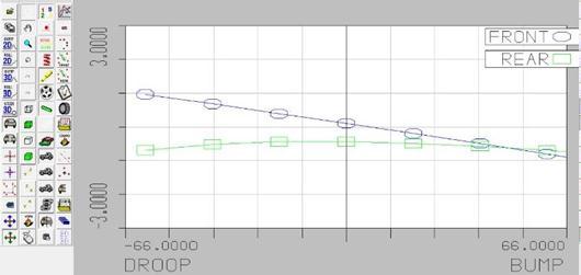
In addition to these fundamental locations, several additional coordinates were adjusted to determine these parameters & values inside the acceptable range. The table of data below includes the final numbers in figure Fig 4, Fig 5, Fig 6
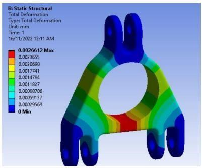
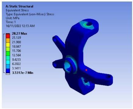
V. FINITE ELEMENT SUSPENSION SYSTEM ANALYSIS.
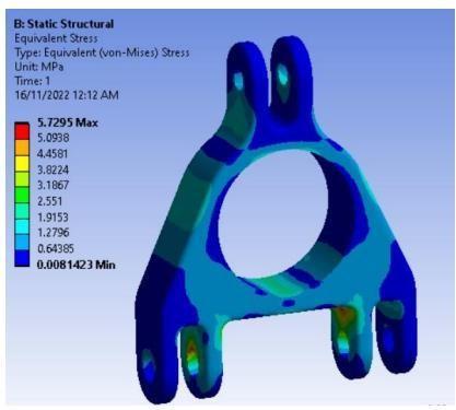
Making use of FEA, it is possible to predict how a component or group will respond to different loaded boundaries and applied loads. The product is assessed and the loads additionally, there are boundary conditions to obtain the best design. A simulation program called Ansys is used to study CAD models and componentsunderdifferentscenariostobeabletocome up with the best design that can withstand the highest appliedload.
Carryingoutstructuralanalysis,thermalanalysisina steady state, fatigue study, etc, is made possible by this software.Weusedstr structural analysiswasemployed, wheretheboundaryconditionsareprovided,togainand improve the results of stress, deformation, and factor of safety[8].Thecomponentsmustbeabletosurviveevery circumstance without failing, which is why the worstcasescenarioisusedtodo thestaticstructural analysis. Thegoalofoptimizationistocreateadesignthatisboth effective and light-weight. The mass and load transfer between sprung and unsprung objects is important in
International Research Journal of Engineering and Technology (IRJET) e-ISSN: 2395-0056

Volume: 10 Issue: 05 | May 2023 www.irjet.net terms of material and design considerations. TABLE III. TABLEIV.
TABLE III. FRONTKNUCKLEMATERIAL.
Material
7075-T6Aluminum
Weightoftheknuckle 0.3221Kg Volume 1.1427e+0.005mm³ Nodes
Material
7075-T6Aluminum
Weightoftheknuckle 0.4231Kg
Volume 1.5057e+005mm³
Nodes 30489
Elements 16424
TotalSprungmass:123kg
TotalUnsprungmass:72kg
TotalWeight:195kg
Fronttrackwidth:45inches
Reartrackwidth:47inches
Staticrideheight:9.8inches
Tyrediameter:22inches
Ridefrequencyfront:2Hz
Ridefrequencyrear:2.5Hz
Spring Constant: w= where, w=amplitude k=springconstant m=sprungmass
Wealsoknowthat,