5 minute read
Suction Duct Optimization for Fume Extraction System

Abstract - The industry is full of processes which are fumegenerating. The vapor, dust, or smoke generated by a substance as a result of burning, explosion or any other related event is termed as fume. It is irritating, harmful and sometimes poisonous. Fumes-producing industrial operations can represent a substantial health and safety risk to workers Extracting fumes from the work station for safety and efficient operation has always been a key engineering issue. This paper focuses on improving the design of suction duct for optimal fume extraction from hot operations such as degreasing and phosphating without increasing the blower capacity ANSYS Fluent is used to evaluate the performance of the proposed design. The results are then compared to the industry standard suction ductdesign.
Key Words: Extraction System, CFD, ANSYS, Suction Duct, CAD, Fluid Flow, Solidworks, Keyshot
Advertisement
1. INTRODUCTION
Fume extraction system comprises of a blower, several inletsasperrequirement,andanenclosedpath.Theendis generally connected to a filtration system. The centrifugal blower creates a negative pressure inside the fume extractor system which extracts out the dust and harmful particles from the inlets and sends it to a contained filtration system. Fume extraction system is a necessity in several industries like mechanical industries where fine metalwork or lasers are used, electrical industries where soldering is done and chemical industries which generate harmfulortoxicfumes.
Thenon-uniformextractionatsuccessiveinletpointsisthe main issue with the fume extraction system of tanks. This results in a larger mass flow rate for extraction from the tank closest to the centrifugal blower. With each tank, the massflowratedecreasesnoticeably,withthefarthesttank having the lowest mass flow rate of extraction. It's crucial toachievesufficientpressureconsistentlyviaall theinlets in order to maximize the extraction process. The typical solution to this issue is to use a blower with a bigger capacity, although doing so considerably increases both costandconsumption.Theprimarygoal ofthisstudyisto suggest design adjustments to the extraction system that will resultin uniform mass flow ratethroughall the inlets usingthecentrifugalblowerofthesamecapacity.
***
1.1 Phosphating
The chemical process of phosphating involves reacting an aqueous phosphate solution with a metallic surface. This produces a metal phosphate conversion layer that is hardly soluble. The material is first washed with acid for thispurpose,andafterthat,thephosphatelayeriscreated. The application of phosphate coating serves as a pretreatment step before coating or painting, enhancing corrosion protection and enhancing the frictional characteristicsofslidingcomponents. Phosphatechemical conversion (PCC) coatings have been investigated for improving surface protection of magnesium alloys in aerospace, automobile, electronics, sports goods, and biomedical applications [1]. Zinc and manganese phosphate coatings are offered by metal coating. These standard processes in industry produce hazardous gaseous effluents. The mists and vapors produced by heated tanks must be removed from the area, since they are dangerous for the workers. The use of extraction and ventilation systems is a necessity in such set-ups to make the working environment free of hazardous gases and fumesefficiently.
1.2 Overview of the simulation
Design of an extraction system depends on many factors, which include, efficiency,cost and scale. There are several advantagesofonedesignandcertaindrawbacksaswell.In thisjournal,wehavecomparedtheconventionalextraction system design (case 1) to a proposed design (case 2). The results of the analysis done are then used to conclude the various advantages of the proposed design over the conventionalone.
Observingtheflowandcalculatingthepressureatboththe inlet and outlet side of the extraction system enables to identify the efficiency of both the systems The mass flow rateattheinletsistakenastheparametertodefinedegree ofextraction.Settingupanexperimentforthesamecanbe atimeandresourceconsumingtask,henceanalysiscomes intoplay.Twodesignmodelsoffumeextractionsystemare analyzedandcomparedusingAnsysFluentinthisjournal. Boththemodelsareanalyzed under the effect ofa blower ofsamecapacity.
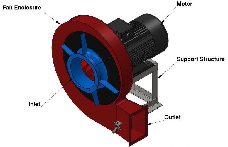
1.3 Centrifugal Blower
A centrifugal blower, also known as a centrifugal fan, is a motor or pump that circulates and moves air. The air is drawn into the blowerand then forced out ata 90o angle. The impeller and the motor are the two major parts of a centrifugalblower.It hashighefficiencyandproducesless noise. The centrifugal blower has relatively small airflow withhighstaticpressure.Itisaspacesavingblowerhence theidealchoiceforfumeextractionsystems.
Ansys Fluent module of Workbench is utilized for the analysis. Meshing is optimized for precision in both the designs and a very fine mesh is generated, with 65247 nodes and 321839 elements in the 2nd case. All inlets are kept at atmospheric pressure whereas the outlet is providedwithamassflowrateof0.4Kg/s,to generatethe suctioneffect.
The extraction system is examined using the K-epsilon model. It is a two-equation model, which implies that two additional transport equations are included to depict the turbulent characteristics of the flow. As a result, a two equation model may take historical influences like convection and turbulent energy diffusion into consideration.
Turbulent kinetic energy, abbreviated k, is the first transferred variable. The turbulent dissipation, or epsilon, it is the variable that determines the scale of turbulence, whereasthefirstvariable,‘k’,determinestheenergyinthe turbulence.
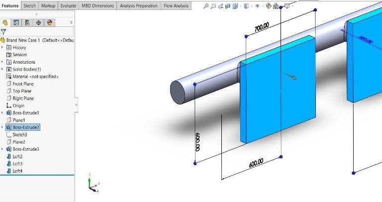
2. DESIGN
The geometry of a fume extractor is the most important part for determining the fluid flow uniformity. In the present study, numerical analysis of the fluid flow characteristics and design optimization of inlet duct geometry for improving flow uniformity are to be done, hence precise design of the models is a must. Designs of bothcase1andcase2aredoneinDSSolidworks2020and renderedinKeyshot9. Theoverall dimensionsofboththe cases are equalized for comparison purpose. The dimensions are with reference to the extraction system used in industries at present. For analysis purpose, the design is made as a solid body and not as a sheet metal designasinreallife.
4.
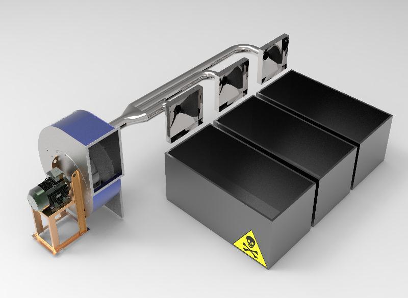
The conventional design of the suction duct (fig 4) of the fumeextractionsystem isoneofthemostcommondesign used in small scale industry due to the design simplicity and affordability. It includes one big main pipe with goes throughout the length of the line and multiple inlet ducts areconnectedtoit.Ablowerisconnectedtooneendofthe mainpipe.Thistypeoffumeextractionsystemcanstillbe found in many small-scale industries. It is very primitive but is easy and cheap to manufacture using sheet metal. There are several drawbacks of this design discussed below.
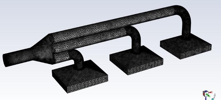
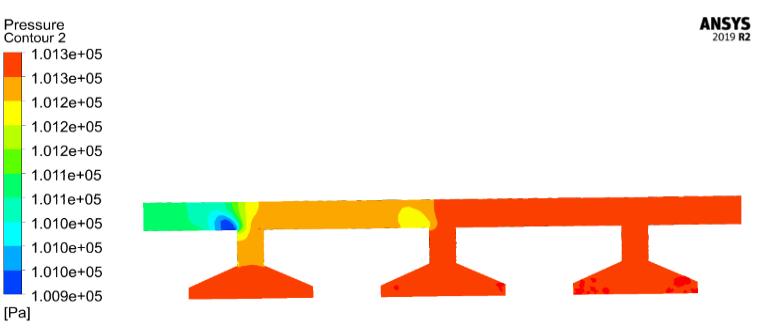
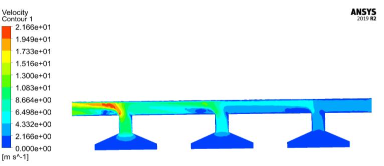
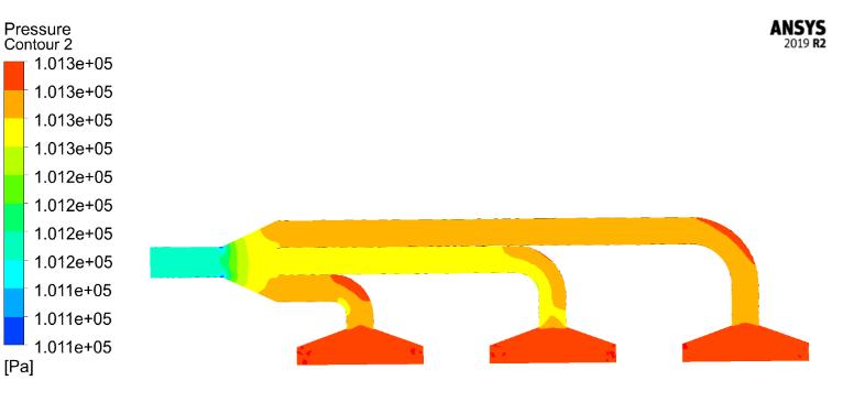
Simulation of the conventional suction duct design is done under the fluent module of ANSYS Workbench 2019 R2.Theresultsofthesamearedisplayedinfig3andfig4 Thevelocitycontour (fig-5)clearlyshowsthereductionin velocity as the number of inlets and distance from the blower end is increased. The pressure contour (fig-6) displays the reduction in pressure as the number of inlets and distance from the blower end is increased. Another importantobservationisthatthepressureandvelocityare hindered at the junction of inlets to the main pipe. Thus there is a sudden change in the flow due to a lack of continuity in the design. All this leads to a lack of suction pressure at the inlet end as we move further from the blower.

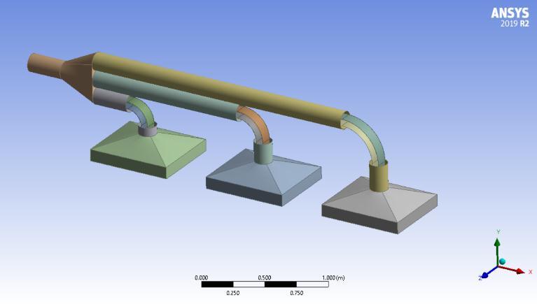
Theproposeddesignofthesuctionduct(fig7)ofthefume extraction system is a new and improved concept that overcomesthedrawbacksoftheconventionalsuctionduct design.Themainfeaturesofthisdesigninclude
1. Individualpathsforeachinlettoreducethetraffic whichincreasesthefluidflow.
2. Junctions are provided with smooth curved path which allows the flow to be continuous and does notgethinderedbyasuddenchangeinpath.
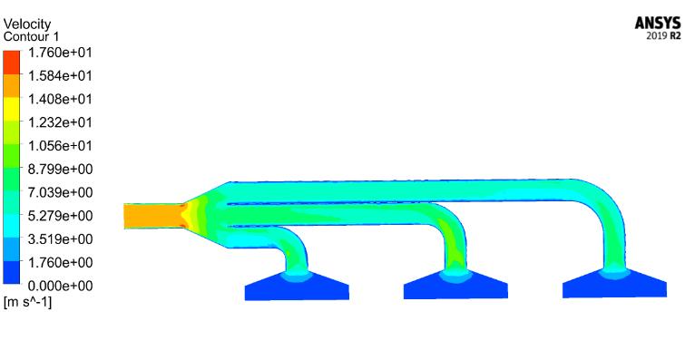
The simulation results confirm the high efficiency and improved flow in the extraction system. As shown in the pressurecontour(fig-8),uniformityinthepressurecanbe seenunlikecase1.Thevelocitycontour(fig-9)verifiesthat the velocityof the fluid hasnoticeably increased at the far endsaswellanddoesnotgethinderedoverthejunctions
Optimization of the conventional design can further be extended with the application of guiding strips inside the extraction system. The guiding strips (fig: 10) further separates the traffic inside of the vent preventing cluster formation. The number of strips to be applied are calculated in reference to the cross section of the vent as wellastheblowerformation.Toomanystripscanhavean adverse effect as they will reduce the area and will act as barriers to the flow, hence it is crucial to decide the number of strips as well as the dimensions of the strips precisely.
7. CONCLUSION
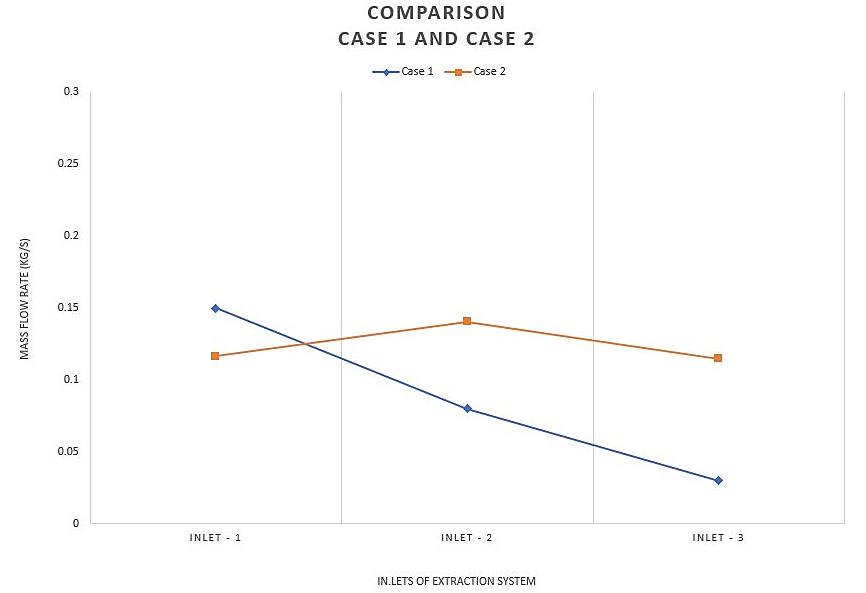
Mass flow rate at every inlet was noted from the results and a graph was plotted for both the case (Suction ducts arerepresentedonXaxisandmassflowrate(Kg/s)onthe Yaxis).Withrespecttotheobservationsmade(refertofig: 11), we can conclude that the proposed design of the suctionducthasincreasedtheuniformityinthemassflow rateatthesuctioninletsthroughouttheextractionsystem. Pressure build-up and fluid flow is also observed to be more uniform even at the junctions. Thus, the proposed design must be considered against the conventional one whentheefficiencyoftheextractionsystemisamust.
References
[1] M. A. Hafeez, A. Farooq, A. Zang, A. Saleem & K. M. Deen “Phosphate chemical conversion coatings for magnesiumalloys:areview”
[2] Anderson, D. A., Tannehill, J. L, and Pletcher, R.H., “ComputationalfluidmechanicsandHeatTransfer"
[3] JohnDavidAnderson,"ComputationalFluidDynamics: TheBasicswithApplications",McGrawHill,NewYork
