
International Research Journal of Engineering and Technology (IRJET) e-ISSN: 2395-0056
Volume: 13 Issue: 05 | May 2026 www.irjet.net p-ISSN: 2395-0072

International Research Journal of Engineering and Technology (IRJET) e-ISSN: 2395-0056
Volume: 13 Issue: 05 | May 2026 www.irjet.net p-ISSN: 2395-0072
ER. VIVEK GAJANAN PIMPALKAR1 , DR. SUCHITA K. HIRDE2
1M.TECH Structural Engineering Student, Applied Mechanics Department, Government College Of Engineering Amravati, Maharashtra, India.
2Guide, Professor and HOD, Applied Mechanics Department, Government College Of Engineering Amravati, Maharashtra, India.
Abstract - Tunnels are enclosed underground passageway except for entrance and exit, dug through the surrounding rock/soil/earth. So, head race tunnel is underground excavated tunnel used to carry water to the powerhouse form the reservoir. Lining of the tunnel is done to minimize the loss of the head, limit the seepage flow inadditionto increasingthe stability of tunnel and avoiding rock particles entering the turbine and prevent it from damage. Therefore, its careful design is important.
Key Words: Head Race Tunnel, Concrete Lining, Induced Tensile Stress, Induced Compressive Stress, Maximum Permissible Tensile Stress, and Maximum Permissible Compressive Stress, Radial and Tangential Spring Stiffness.
The headrace Tunnel carries water from intake to the powerhouse by connecting the de-silting chamber to the surgeshaft,fromwherewaterisfurthercarriedtoturbines in powerhouse. From constructability point of view a DShapeoramodifiedD-Shapetunnelispreferredasitgives betterprogressforsmallsizetunnel.Thesizeofthetunnel shallbesuchthattheequipmentbeingusedforconstruction canmanoeuvreeasilyforgoodprogressofthetunnelboring. However,thefinishedshapeofthetunnelmaybedifferent–circular, horse-shoe, modified horse-shoe, D-shape or egg shaped. Structurally a circular shape tunnel is preferable thanaD-shapetunnel.Horseshoeormodified-horseshape tunnel is a compromise between circular and D-shape sections. This paper covers concrete lining design of head racetunnel.
The tunnel would be concrete lined in its entire length; thicknessofliningwillvarydependinguponthetypeofrock andwaterpressure.
Thetunnelisexcavatedusingtheconventionaldrilland blast method. After excavation, adequate rock support measures are taken to avoid collapsing of rocks. The excavationprofileismonitoredforconvergenceofopening. With passage of time the deformations will stabilize and reachequilibrium.Afterattainmentofthisstage,liningisto
beprovided.Headracetunnelliningisconcretelineddueto followingreasons-
• Minimize the head losses due to friction in the tunnel.
• Prevent/limittheseepageflows
• Preventthelooserockparticlesentryintoturbineby preventingerosionandwashingoutofjointfillings
• Ensurelongtermstabilityoftunnelundervarying hydrostaticandhydrodynamicloadconditions.
The concrete lining of headrace tunnel is essentially plannedasun-reinforcedthatiseasiertoplace,has better qualityandismoredurable.Leakageintoandfromthetunnel iseffectivelyreducedbysystematicgroutingtherockaround tunnel. However, in reaches where the tunnel will pass throughverypoorrock(ClassV)ortunnelrockcoverislow, reinforced concrete lining may be required. Design of reinforced concrete lining shall be carried out during executionstageasperactualsitecondition.
The choice of lining thickness is generally based on practicalconsiderations;asapreliminaryestimate,IS:4880 (PartIV):1971,clause7.2recommendsaliningthicknessof about 6cm for every m of finished diameter of tunnel (circular),withapracticalminimumforsuccessfulconcreting of 150mm for unreinforced concrete and 300mm for reinforcedconcrete.
Thicknessofliningshallbesuchthattheinducedstressin concretedoesnotexceedtheallowablestressforparticular gradeofconcrete.
Loadsactingonconcreteliningandtheiruseindesignare discussedbelow:
Deadloadofconcreteliningiscalculatedfromconcrete volumestakenofffromphysicaldimensionsofthehead racetunnel.Self-weightoftheliningmustbeconsideredas deadload.
International Research Journal of Engineering and Technology (IRJET) e-ISSN: 2395-0056
Volume: 13 Issue: 05 | May 2026 www.irjet.net p-ISSN: 2395-0072
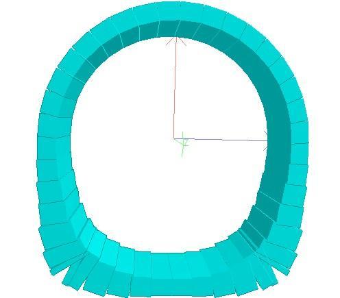
3.2 Internal Hydrostatic Pressure:
Thehydrostaticpressureactingonconcretelininginternally is equivalent to a column of water calculated as difference between full reservoir level and tunnel invert at any particularlocation.
Duringtheinitialfillingofthetunnel,thewaterpressurein thesurroundingrockwillstarttoincrease.Duetopresence ofradialandlongitudinalcracksinlining(duetoshrinkage, temperature, construction joints), there is a tendency of balancingofpressureoneithersideoftunnel.Duetotimelag inbalancingofthepressure,somenetinternalpressurewill act on the lining at any given time during the filling up operation.Evidently,locationofmaximuminternalpressure willbejustupstreamofsurgeshaft.
Maximum internal pressure head acting on the lining (at tunnelsectionjustupstreamofsurgeshaft)iscalculatedas:hi =FRL–Tunnelinvert
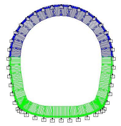
3.3 Transient Hydrostatic Pressure:
During transient surge condition, the time period of the hydraulictransientbeingverysmall,theexternalandinternal waterpressurewouldnothavesufficienttimetobalanceout andsomedifferentialpressurewill,therefore,willbeexerted onthelining.However,effectofthistransientloadingduring normaloperationismuchlesscomparedtoinitialfillingof tunnelcondition,hencecanbeignoredwhilecalculation.
During dewatering of tunnel, the internal pressure on the liningisreducedtozeroandexternalpressurewilldevelop duetopressureexertedbywaterfromoutside.Theheadrace tunnelsectionnearupstreamofsurgeshaftwillbesubjectto maximum external pressure, as external pressure is calculatedasthedifferencebetweenfullreservoirleveland invertoftunnelatlocationofinterest.
Thus, maximum external pressure head working on the lining:
hext=FRL–Tunnelinvertnearsurgeshaft
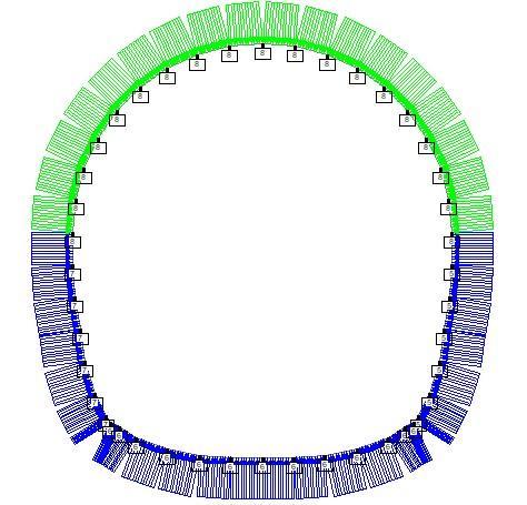
3.5 Grouting Pressure:
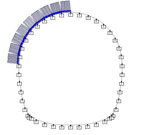
Contact grouting/ consolidated grouting is to be done betweentheliningandthesurroundingrockmasstoensure uniform contact and proper transfer of internal water pressure from lining to the rock mass. Generally, contact grouting is done at assumed maximum pressure and the lining design has to be verified to safely resist this grout pressure.Aftercompletionofexcavation,concreteliningof tunnelisstarted.Theassumedcontactgroutingpressure,act on lining as external pressure. The lining thickness is checked for its adequacy. Also, maximum permitted grout pressureoverareaontheliningisequaltoone-quarterofthe tunneldiameter(asshowninFigure-4),andamaximumof 1.5m(i.e.5ft)(ReferUSArmyCorpsofEngineers,EM-11102-2901,Box9-1,Page9-8).
Volume: 13 Issue: 05 | May 2026 www.irjet.net p-ISSN: 2395-0072
3.6 Rock Loads:
Due to considerable time difference between tunnel excavationandinstallationofconcretelining,allrockloads are assumed to be fully supported by permanent rock supports.
Relaxationofrockandstressredistributionisconsideredto befullystabilizedpriortoinstallationofconcretelining.As such, no rock loads from excavation are assumed to be transferredtotheliningormayvaryaspersitecondition.
3.7 Seismic Loads:
Generally,locationofHeadracetunnelisundergroundwhere super-incumbentcovervaries,duetothiscovertheeffectof groundmotionwillreducesubstantially.Becausetheliningis indirectcontactwithfullygroutedsurroundingrock,during earthquake the system will oscillate as a single unit. Thus, therewillnotbeanydynamicloadingontheconcretelining. Duetothisreason,seismicloadsarenotconsideredforthe designoflining.
3.8 Temperature Loads:
Temperaturedifferenceoneithersideofliningisassumedto be insignificant; as such temperature loading has not been accountedforthedesignofTunnel.
4.
Duringtheservicelifeofthetunnel,tunnelliningissubjected to different loading conditions. Combinations to be consideredforanalysisare:-
(i) NormalOperationCase:
External and internal water pressures are balanced due to water seepage through the concrete (due to presence of radial and longitudinal cracks in lining) and surrounding rock.
(ii) InitialWater-fillingCase:
Externalwaterpressurehasnotyethadtimetobalancethe internalwaterpressure,resultinginternalwaterpressureto actoutwards.
(iii)TunnelDewateringCase:
Intakegateclosed;thetunnelhasdrainedthroughtheturbine whilethewicketgateisclosing.So,Externalwaterpressureis actinginwards.
(iv)TunnelConstructionCase:
Loadingduetogroutingduringconstruction
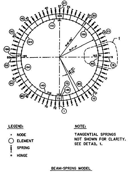
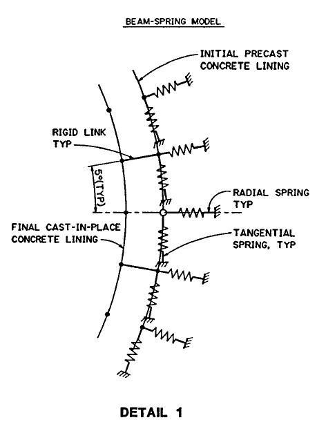
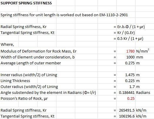
FEManalysiscanbecarriedoutusingSTAADProsoftware. Beamelementshavebeenmodelledtoanalysethestructure. Compression only surface spring (modulus of subgrade reaction) is considered to generate the support condition. Tangential and radial springs are applied at each node to simulateelasticinteractionbetweentheliningandtherock. The interface between lining and rock cannot withstand tension; therefore, interface elements may be used or the springs deactivated when tensilestresses occur. Thus,rock participationwhereverrequiredwillbetakencareofbythis compression only spring. The radial and tangential Spring stiffnesses for unit length of tunnel lining is worked out basedonUSArmyCorpsofEngineers,EM-1110-2-2901by usingfollowingformula:-
Kr =Er.b.θ/(1+μr)
Kt =Kr /(G.Er)=0.5Kr /(1+μr)
Where, Kr and Kt = radial and tangential spring stiffnesses respectively
G=shearmodulus
θ=arcsubstendedbythebeamelement(radian)
International Research Journal of Engineering and Technology (IRJET) e-ISSN: 2395-0056
Volume: 13 Issue: 05 | May 2026 www.irjet.net p-ISSN: 2395-0072
b=lengthoftunnelelementconsidered
The value for modulus for deformation, Er can be obtained fromequationsinEM-1110-2-2901orcanbecalculatedby using geotechnical design data i.e. GSI, mi, D (disturbance factor)etc.onsoftwarelikeRoclab.
All the possible loads are applied under suitable load combinationsandanalyzed.Analysisisdoneusingsoftware andinducedstressesintheliningareobtainedandthickness ofliningshallbesuchthattheinducedstressinconcretedoes not exceed the allowable stress for particular grade of concretewhichisbeingusedforlining.
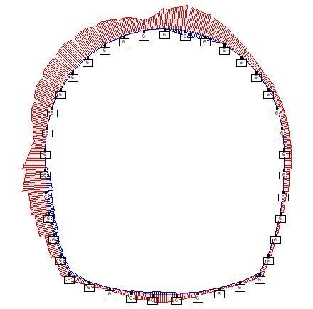
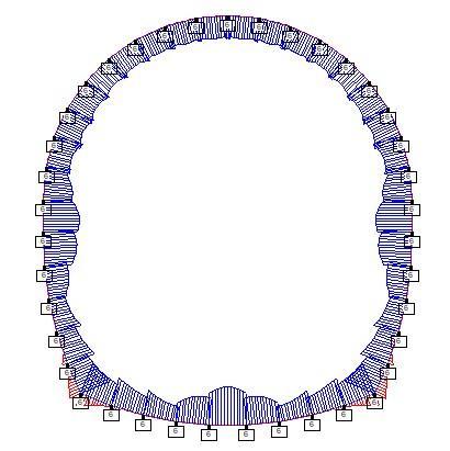
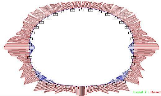
The stress diagram obtained for the various loading combinationsareasfollows:
Now,hereisanexampletoillustratethedesignofliningfor headracetunnelonSTAAD.
Let us consider a case where, the tunnel invert level be EL 1025.76mandFRLbeEL1080.60m.Now,calculatingallthe valueasdiscussedaboveandputtingitinSTAAD.
Ahorse-shoeconcreteliningof225mmismade,takingthe centre of lining distributing the lining in beam elements of equalsize.
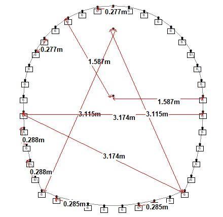
Loadstobeconsideredforanalysis(ReferFigure1,2,3&4) are–
1. DeadLoad =SelfweightofConcreteLining
2. InternalHydrostaticPressure,
Pi=(FRL–Tunnelinvertlevel)x9.8kN/m
=0.5(1080.6m–1025.76m)x9.8
≈270.00kN/m
(headlossofabout50%maybesafelyconsidered)
3. ExternalHydrostaticPressure,
Pe=(FRL–Tunnelinvertlevel)x9.8kN/m
=0.5(1080.6m–1025.76m)x9.8
≈270.00kN/m
(headlossofabout50%maybesafelyconsidered)
4. GroutPressure,Pg=250kN/m(assumed)
Modulusofdeformation,Erfortherockisnowcalculatedon basisofgeotechnicaldesigndatausingRoclab,comestobe 1780N/mm2. CalculatingSpringStiffnessesusingthisvalue:
International
Volume: 13 Issue: 05 | May 2026 www.irjet.net p-ISSN: 2395-0072
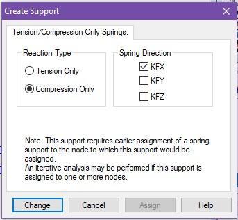
Thespringstiffnessesareassignedtothesupportandrefis defined(centrecoordinatesofradiusoflining)forindividual arc.Thevalueofcoordinates(forref)changesaccordingto centreofthearconwhichthatsupportistobeassigned.Also, thesupportsaredefinedascompressiononly.
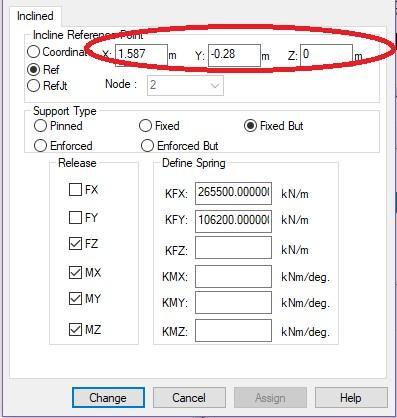
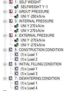
Now,afterassigningthesupportsandabovecalculatedloads ontheliningelements,criticalloadcombinationsareapplied andliningischeckedforloadingconditions.Afteranalysis, themaximumtensilestressandmaximumcompressiveStress in N/mm2 and Stress diagram (refer figure-5,6 & 7) are obtained from post processing option, which is further comparedwithmaximumallowabletensileandcompressive Stress.
-1: Comparison of induced & allowable Stresses (225
Similarly,Ahorse-shoeconcreteliningof300mmismade, takingthecentreofliningdistributingthelininginbeam elementsofequalsize.Repeatingthesameprocessforthe designandanalysiswithreinforcement.Belowarethe results:-
Table -2: Comparison of induced & allowable Stresses (300 mm thickness reinforced) Sr.
Lining
Result Safe Safe
Similarly,Ahorse-shoeconcreteliningof325mmismade, takingthecentreofliningdistributingthelininginbeam elementsofequalsize.Repeatingthesameprocessforthe designandanalysiswithreinforcement.Belowarethe results:-
Table -3: Comparison of induced & allowable Stresses (325 mm thickness reinforced)
Sr. No. Loading Condition Induced Stress in Lining due to applied Load
Result Safe Safe
The lining is safe without reinforcement structurally, but nominal reinforcement is recommended for durability and crackcontrolfor225mm,300mm,325mthicknesses
International Research Journal of Engineering and Technology (IRJET) e-ISSN: 2395-0056
Volume: 13 Issue: 05 | May 2026 www.irjet.net p-ISSN: 2395-0072
STAADFILE
STAADSPACE
STARTJOBINFORMATION
ENGINEERDATE20-April-17
ENDJOBINFORMATION
INPUTWIDTH79
UNITMETERKN
JOINTCOORDINATES
21.58700;31.562890.275580;41.491290.5427860;5 1.374380.79350;61.215711.02010;71.02011.215710;8 0.7935 1.37438 0; 9 0.542786 1.49129 0; 10 0.27558 1.562890;119.71725e-0171.5870;12-0.275581.562890; 13-0.5427861.491290;14-0.79351.374380;15-1.0201 1.215710;16-1.215711.02010;17-1.374380.79350;18 -1.49129 0.542786 0; 19 -1.56289 0.27558 0; 20 -1.587
1.94345e-016 0; 21 1.587 -0.28 0; 22 -1.587 -0.28 0; 23 1.57394-0.5676680;241.53486-0.8529680;251.47008
-1.133550;261.38014-1.407110;271.26577-1.671390; 28-1.57394-0.5676680;29-1.53486-0.8529680;30 -1.47008-1.133550;31-1.38014-1.407110;32-1.26577
-1.671390;34-1.00001-1.775270;35-0.725863-1.85440; 36 -0.445624 -1.9081 0; 37 -0.161645 -1.93595 0; 38 1.00001-1.775270;390.725863-1.85440;400.445624
-1.90810;410.161645-1.935950; MEMBERINCIDENCES
123;234;345;456;567;678;789;8910;91011; 101112;111213;121314;131415;141516;151617; 161718;171819;181920;202022;262228;272829; 282930;293031;303132;313234;323435;333536; 343637;393741;404140;414039;423938;433827; 442726;452625;462524;472423;482321;49212.
DEFINEMATERIALSTART
ISOTROPICCONCRETE
E2.5e+007
POISSON0.17
DENSITY24
ALPHA1e-005
DAMP0.05
TYPECONCRETE
STRENGTHFCU25000
ENDDEFINEMATERIAL
MEMBERPROPERTYINDIAN
1TO18203949PRISYD0.225ZD1
MEMBERPROPERTYINDIAN
2648PRISYD0.246ZD1
2747PRISYD0.291ZD1
2846PRISYD0.326ZD1
2945PRISYD0.4125ZD1
3044PRISYD0.5025ZD1
3440PRISYD0.258ZD1
3341PRISYD0.316ZD1
3242PRISYD0.4125ZD1
3143PRISYD0.5025ZD1
CONSTANTS
BETA180MEMB2026TO3439TO49
MATERIALCONCRETEALL SUPPORTS
2TO20INCREF000FIXEDBUTFZMXMYMZKFX
265500KFY106200
2228TO31INCREF1.587-0.280FIXEDBUTFZMXMY MZKFX265500KFY106200
2123TO26INCREF-1.587-0.280FIXEDBUTFZMXMY MZKFX265500KFY106200
273234TO41INCREF01.1750FIXEDBUTFZMXMY MZKFX265500KFY106200
SPRINGCOMPRESSION
2TO3234TO41KFX
LOAD1LOADTYPENoneTITLESELFWEIGHT
SELFWEIGHTY-1
LOAD2LOADTYPENoneTITLEGROUTPRESSURE MEMBERLOAD
10TO18UNIY-250
LOAD3LOADTYPENoneTITLEINTERNALPRESSURE MEMBERLOAD
2026TO3439TO49UNIY270
1TO18UNIY270
LOAD4LOADTYPENoneTITLEEXTERNALPRESSURE MEMBERLOAD
1TO18UNIY-270
2026TO3439TO49UNIY-270
LOADCOMB5CONSTRUCTIONCONDITION
11.021.0
LOADCOMB6INITIALFILLINGCONDITION
11.031.0
LOADCOMB7DEWATERINGCONDITION
11.041.0
PERFORMANALYSIS
FINISH
Theinducedstressesintheliningi.e.maximumtensilestress and maximum compressive Stress are obtained in N/mm2 andthicknessofliningshallbesuchthattheinducedstressin concretedoesnotexceedtheallowablestressforparticular gradeofconcretewhichisbeingusedforliningandincase
International Research Journal of Engineering and Technology (IRJET) e-ISSN: 2395-0056
Volume: 13 Issue: 05 | May 2026 www.irjet.net p-ISSN: 2395-0072
the induced stress exceeds allowable stress, the lining thicknessmaybeincreasedorreinforcementcanbeprovided fortheexceedingstress.Basedonthecompleteanalysisand designverification,thefollowingconclusionswereobtained:
1. The concrete lining is structurally safe under all consideredloadingconditions.
2. Theoriginal 225 mm lining thickness satisfiesthe permissiblestresscriteriaspecifiedinIS456.
3. Increasingtheliningthicknessto 300 mm & 325 mm furtherimprovessafety,stiffness,anddurability whilereducinginducedstresses.
4. The maximum induced tensile and compressive stresses remain within permissible limits for M25 concrete.
5. Compression-only spring supports effectively simulaterealisticrock-lininginteraction.
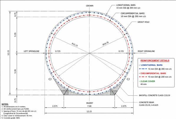
6. Reinforcement is not structurally required, but nominal reinforcement is recommended for crack controlanddurability.SuggestedReinforcementfor 300mmand325mmthickness: Longitudinal Bars: 10 mm diameter @ 200 mm c/c ,CircumferentialBars: 10 mm diameter @ 200 mm c/c ;ClearCover: 40 mm
7. The tunnel lining system is expected to perform satisfactorilyduringconstruction,initialfilling,and dewateringconditions.
8. Theproposeddesigniseconomical,safe,andsuitable forlong-termhydropowertunnelapplications.
[1] USArmyCorpsofEngineers(USACE),Tunnelsand ShaftinRock,EM-1110-2-2901
[2] HydroPowerStructuresbyR.S.Varshney
[3] IS456:2017-PlainandReinforcedconcrete-codeof practice
[4] ITA Working Groupon General Approaches to the DesignofTunnels(1988)“GuidelinesfortheDesignof Tunnels”,TunnellingandUndergroundSpaceTechnology, Vol.3,No.3,pp.237-249.
[5] DuddeckH andErdmannJ.(1982)“StructuralDesign ModelsforTunnels”,TunnellingInstitutionofMiningand Metallurgy,pp.83-91.
[6] MuirWood,A.M.,1975.Thecirculartunnelinelastic ground.Geotechnique25(1),115–127.