
International Research Journal of Engineering and Technology (IRJET) e-ISSN: 2395-0056
Volume: 13 Issue: 05 | May 2026 www.irjet.net p-ISSN: 2395-0072

International Research Journal of Engineering and Technology (IRJET) e-ISSN: 2395-0056
Volume: 13 Issue: 05 | May 2026 www.irjet.net p-ISSN: 2395-0072
T Eswaran1 , G Peter Packiaraj2 , A Murugan3 , C Indra Kumar4
1Final year B.E Marine & PSN CET, Tirunelveli, Tamil Nadu.
2,4Assistant Professor, Dept. Of Marine Engineering, PSN CET, Tirunelveli, Tamil Nadu.
3Professor, Dept. Of Marine Engineering, PSN CET, Tirunelveli, Tamil Nadu.
***
ABSTRACT-This paper presents a conceptual design for an auxiliary electrical generation system aboard marine vessels, exploiting the natural hydrostatic pressure of seawater below the ship's waterline as a primary energy source. A turbine coupled to a generator rotor is driven by seawater admitted through a sub-waterline sea chest. To overcome the inherently limited pressure differential available at typical ship drafts, a Venturi nozzle is integrated into the existing high-temperature (HT) cooling water circuit. The low-pressure region created at the Venturi throat is applied to the turbine outlet, thereby increasingtheeffectivepressuredropacrosstheturbineand enhancing rotor speed and electrical output. After passing throughtheturbine,theseawaterisdirectedthroughtheHT cooler as the normal cooling medium before being dischargedoverboard.Theconceptisevaluatedwithrespect to thermodynamic feasibility, energy balance, and practical integration within conventional marine cooling architectures.
Keywords: Marine auxiliary power, seawater turbine, hydrostatic pressure, Venturi nozzle, HT cooling system, onboard electricity generation, energy recovery, marine energy efficiency, turbine- generator system, sustainable marine.
The maritime industry is under increasing pressure to reduce fuel consumption and auxiliary machinery losses. Ships carry large quantities of seawater for cooling purposes water that is already in motion, pressurized by the vessel's draft, and ultimately discharged overboard without energy recovery. This represents an unexploited low-grade energy stream presentonvirtuallyeveryocean-goingvessel.Theconcept explored here is to intercept this flow at the point of highestavailablepressurebelowthewaterlineandextract useful work from it before it serves its primary cooling function. The principal challenge is that the hydrostatic headavailableatnormaloperatingdrafts(typically5to15 meters)ismodest,andadirect-driveturbineoperatingon
thisheadalonewould produceinsufficientshafttorque to generatemeaningfulelectricalpower.
To address this, the proposed system couples the turbine outlet to a Venturi nozzle installed in the parallel HT cooling seawater line. The pump already driving that line creates a high-velocity jet at the Venturi throat, producing a low-pressure (suction) zone. By connecting this zone to the turbine exhaust, a secondary pressure differential is imposed across the turbine rotor, augmenting the primary hydrostatic head and increasing flowvelocityandturbinerotationalspeed.
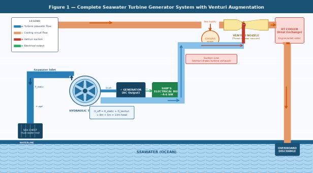
Figure1-Completesystemschematicshowingseachest inlet,turbine-generatorassembly,VenturinozzleintheHT coolingcircuit,andoverboarddischargepath.
Seawater is admitted through a dedicated sea chest positioned below the vessel's loaded waterline. The available hydrostatic pressure P_static at the turbine inlet isgivenby: P_static=ρ×g×d
International Research Journal of Engineering and Technology (IRJET) e-ISSN: 2395-0056
Volume: 13 Issue: 05 | May 2026 www.irjet.net p-ISSN: 2395-0072
whereρisthedensityofseawater(approximately 1,025 kg/m³), g is the gravitational acceleration (9.81 m/s²), and d is the depth below the waterline at the sea chest centreline. For a typical bulk carrier at d = 8 m, this yields approximately 80.2 kPa a relatively modest differential when compared to the ambient back-pressure attheturbineoutlet.
The turbine is an axial or mixed-flow hydraulic turbinewhoseshaftismechanicallycoupledtotherotorof a synchronous or permanent-magnet generator. The turbineisdesignedtoaccepttheavailableseawaterflowat theinletpressureandconvertkineticandpotentialenergy intorotationalmechanicalenergy.Thegeneratorproduces alternating current, which may be rectified and conditionedtosupplementthevessel'selectricalbus.
In the baseline configuration (without Venturi augmentation), the net head across the turbine is limited to the hydrostatic head at the sea chest minus pipeline frictionallosses,yieldingalowspecificpoweroutput.This alone is generally insufficient for practical power generation beyond micro-watt scales without very large turbinediameters.
The key innovation is the application of a Venturi nozzle to increase the effective pressure drop across the turbine.The Venturiisinstalledin the existingHT cooling seawater delivery line, which is driven by the vessel's dedicatedcoolingseawaterpump.
As the cooling water accelerates through the convergent section of the Venturi nozzle, static pressure dropsinaccordancewithBernoulli'sprinciple: P₁+½ρv₁²=P₂+½ρv₂²
Atthe throat(minimum cross-section),velocityis maximised and static pressure P_throat is minimised. If P_throat is below the pressure at the turbine outlet, a net suctionforcedrawswaterthroughtheturbinecircuit.The turbine outlet is connected to the Venturi throat via a dedicated suction line, effectively placing the throat pressureastheturbineback-pressure.
Thetotaleffectiveheaddrivingtheturbinethusbecomes: H_eff=H_static+H_Venturi
where H_Venturi = (P_atm P_throat) / (ρg) represents the additional suction head created by the Venturi arrangement. This can theoretically approach the cavitation limit approximately 10.3 metres of equivalent water column at sea level though practical limits due to dissolved gas release and vapour pressure constrain it to approximately6to8metresofadditionalequivalenthead.
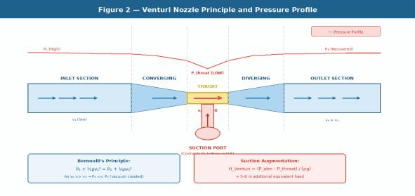
Figure2 Venturinozzlecross-sectionshowing convergent-divergentgeometry,velocityandpressure profiles,andthesuctionportconnectiontotheturbine outlet.
After passing through the turbine, the seawater still cool and pressurised by the Venturi pump's delivery enters the HT cooler as the normal cooling medium. It absorbsheatfromtheenginejacketwatercircuitandexits at elevated temperature before being discharged overboard via the ship's side valve arrangement. This dual-use of the seawater stream ensures that the turbine installation imposes no additional seawater consumption and does not disturb the cooling system's thermal performance, provided the additional flow resistance introducedbytheturbineiswithinthepump'scapacity.
Thehydraulicpoweravailabletotheturbineis:
P_hydraulic=η_turbine×ρ×g×Q×H_eff where Q is the volumetric flow rate (m³/s) through the turbine and η_turbine is the turbine efficiency (typically 0.70 to 0.85 for well-designed hydraulic turbines). The generatedelectricalpowerP_elecisfurtherreducedbythe generatorefficiencyη_gen(typically0.90to0.95):
P_elec=η_turbine×η_gen×ρgQH_eff
International Research Journal of Engineering and Technology (IRJET) e-ISSN: 2395-0056
Volume: 13 Issue: 05 | May 2026 www.irjet.net p-ISSN: 2395-0072
ItmustbenotedthattheVenturiaugmentationis not a free energy source. The Venturi nozzle introduces additional resistance into the HT cooling circuit, which increases the head against which the cooling seawater pumpmustoperate.Thisincreasesthepump'sshaftpower demand,whichisultimatelysourcedfromthemainengine or auxiliary generator. A rigorous energy audit must confirm that the electrical output from the turbine generator exceeds the additional pump power demand attributabletotheVenturi,accountingforallefficienciesin thechain.
Thenetenergygainconditionis:
P_elec>ΔP_pump/(η_motor η_pump) where ΔP_pump is the additional pump shaft power and η_motor, η_pump are the motor and pump efficiencies respectively. This condition represents the fundamental viabilityconstraintfortheproposedsystem.
For illustrative purposes, consider the following design parameters:
necessary to confirm net positive output for a specific vesselapplication.
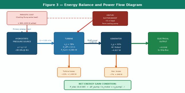
Figure3 Energybalanceandpowerflowdiagram showinghydraulicinput,turbineandgenerator efficiencies,parasiticpumpcost,andnetelectricaloutput
The turbine must be designed for low-head, moderate-flow operation. Axial flow (propeller-type) or mixed-flow turbines are the most appropriate candidates at the flow rates and heads anticipated. The runner diameter, blade angle, and rotational speed must be matched to the effective head and flow rate to maximize efficiency. Variable-pitch blades may be considered to accommodate varying vessel drafts and cooling circuit conditions.
The Venturi nozzle must be designed to achievea throat pressure sufficiently below the turbine outlet pressurewithoutinducingcavitationinthecoolingcircuit. The throat-to-pipe area ratio, convergent angle, and divergent recovery section geometry all affect the achievablesuctionandthepressurerecoverydownstream of the throat. The nozzle must be constructed from corrosion-resistant materials suitable for continuous seawaterservice.
These figures indicate a potentially useful supplementary power output, though a detailed pump energy audit is
TheintroductionofaturbineandVenturiintothe HTcoolingcircuitwillalterflowresistanceandpotentially reduce cooling flow rates to the HT cooler if the existing pumpisoperatingnearitsdutypoint.Adetailedhydraulic network analysis of the combined circuit is essential. It
International Research Journal of Engineering and Technology (IRJET) e-ISSN: 2395-0056
Volume: 13 Issue: 05 | May 2026 www.irjet.net p-ISSN: 2395-0072
maybenecessarytoupratethecoolingpumportoinstalla dedicated pump for the Venturi line, separate from the maincoolingpump.
Allwettedcomponentsmustbefabricatedfromor coated with seawater-resistant materials such as duplex stainless steel, naval bronze, or fibre-reinforced polymer composites. Biofouling management including cathodic protection and periodic cleaning is essential for the long-term reliability of the turbine runner and nozzle throat. Provision for isolation valves and bypass arrangements is required to enable maintenance without disruptingthevessel'scoolingsystem.
Any auxiliary power generation system installed aboard a classed vessel must comply with the requirements of the relevant classification society (e.g., Lloyd's Register, DNV, Bureau Veritas). The system must demonstrate that it does not compromise the integrity of the hull, the reliability of essential cooling services, or the electrical safety of the ship. Relevant rules for sea chests, coolingsystems,andauxiliarymachinerywillapply.
5.
The proposed concept is, at its core, a low-head hydraulic turbine with Venturi-assisted back-pressure reduction. The physics are well-established, and there is no thermodynamic barrier to the concept. The critical question is whether the net electrical output justifies the additional capital cost, maintenance burden, and engineeringcomplexityoftheinstallation.
The Venturi augmentation is a particularly importantinnovation.Withoutit,thehydrostaticheadata seachestisgenerallytoosmalltodriveaturbineatuseful rotational speeds and power outputs. With Venturi augmentation, the effective head is nearly doubled, which giventhatpowerscaleswiththeproductofheadandflow roughlydoublesthepoweroutputpotential.However,this is at the cost of additional pump work, which must be carefullyquantified.
Thesystemismostattractiveonvesselswithhigh draft (e.g., laden bulk carriers and tankers), high cooling water flow rates, and long operational periods at consistent trim. Passenger vessels and naval vessels with high continuous auxiliary power demands may also be suitable candidates. Vessels operating in warm tropical
waters, where cooling demands are highest and cooling flow rates are largest, represent the most promising applicationenvironment.
A potential concern is whether the seawater drawnthroughtheturbine undergoessufficienttreatment priortouseintheHTcooler.Instandardcoolingsystems, seawater passes through strainers. If the turbine circuit bypassesthemainstrainer,additionalfiltrationprovisions willberequired
• Computationalfluiddynamics(CFD)simulationof the combined turbine-Venturi circuit to optimize geometryandpredictcavitationmargins.
• Construction and testing of a scaled laboratory prototype to validate the effective head augmentation and turbine power output predictions.
• Full hydraulic network modelling of the ship cooling system, including the proposed circuit, to determinepumpdutypoint changesandrequired pumpmodifications.
• Detailed energy balance analysis for at least two representativevesseltypes(e.g.,ladenVLCCanda Panamax bulk carrier) to quantify realistic net electricaloutput.
• Evaluation of alternative augmentation methods (e.g.,ejectorpump,electricmotor-drivenbooster) ascomparatorstotheVenturiapproach.
• Assessmentofclassificationsocietyrequirements anddevelopmentofatype-approvaltestprotocol.
Thispaperhaspresentedaconceptualdesignfora seawater-driven auxiliary turbine generator system enhancedbyVenturi-assistedsuction.Thesystemexploits the hydrostatic pressure of seawater below the ship's waterline and uses the low-pressure region at a Venturi throat integrated into the HT cooling circuit to augment theeffectivepressuredropacrosstheturbine.Theturbine outlet flow is then utilised as the HT cooler cooling medium before overboard discharge, making the arrangementdual-purposeandminimisingwaste.
Preliminary analysis suggests that net electrical generationintherangeofseveralkilowattsistheoretically achievable on vessels with adequate draft and cooling waterflow.Theconceptisphysicallysoundandrepresents anovelapproachtoshipboardenergyrecovery.Significant engineering development, including prototype testing and
International Research Journal of Engineering and Technology (IRJET) e-ISSN: 2395-0056
Volume: 13 Issue: 05 | May 2026 www.irjet.net p-ISSN: 2395-0072
fullenergy-balanceverification,isrequiredtoadvancethe conceptfromfeasibilitytopracticalimplementation.
If validated, the system could contribute meaningfully to reducing a vessel's auxiliary diesel generator load, thereby reducing fuel consumption and exhaustemissionsalignedwiththeInternationalMaritime Organization's strategy for greenhouse gas reduction in shipping.
1. Munson, B.R., Young, D.F., Okiishi, T.H. (2013). FundamentalsofFluidMechanics.7thed.Wiley.
2. White, F.M. (2011). Fluid Mechanics. 7th ed. McGraw-Hill.
3. MAN Diesel & Turbo. (2018). Basic Principles of ShipPropulsion.MANEnergySolutions.
4. International Maritime Organization. (2023). Strategy on Reduction of GHG Emissions from Ships.MEPC.377(80).
5. Kaplan, V. (1913). Eine neue Turbinenkonstruktion. Proceedings of the Vienna AcademyofSciences.
6. Lloyd'sRegister.(2022).RulesandRegulationsfor theClassificationofShips.Lloyd'sRegisterGroup.