
International Research Journal of Engineering and Technology (IRJET) e-ISSN: 2395-0056
Volume: 13 Issue: 05 | May 2026 www.irjet.net p-ISSN: 2395-0072

International Research Journal of Engineering and Technology (IRJET) e-ISSN: 2395-0056
Volume: 13 Issue: 05 | May 2026 www.irjet.net p-ISSN: 2395-0072
Mr. Aniket S. Kadekar1 , Dr. Dipak S. Patil2
1Mtech student, Heat Power Engineering, Department of Mechanical Engineering, G H Raisoni College of Engineering and Management, Pune, Maharashtra, India
2Professor, Department of Mechanical Engineering, G H Raisoni College of Engineering and Management, Pune, Maharashtra, India
Abstract - This research explores the significance of energy conservation in the context of rising energy consumption and its impact on economic growth. With a focus on cooling systems, particularly evaporative condenser technology, the study aims to investigate its fundamentals, operating principles, and theoretical aspects. Evaporative condensers and cooling towers are critical components in industrial cooling systems, playing a vital role in dissipating heat from processes and maintaining operational efficiency. However, losses in these systems, both in terms of water and energy, can significantly impact performance, environmental sustainability, and operational costs. This research addresses methods and strategies for controlling losses in evaporative condensers and cooling towers, focusing on water consumption, energy efficiency, and system performance optimization. Key factors such as chemical consumption, evaporation, leakage and heat exchange inefficiencies are analyzed. The paper discusses technological advancements, maintenance practices, and control systems that can minimize these losses, including the use of advanced water treatment processes, airflow management, and energy recovery solutions. By adopting these control measures, industries can achieve reduced operational costs, minimized environmental impact, contributing to the overall sustainabilityofindustrialcoolingprocesses.
Key Words: Evaporative condensers, cooling towers, energy conservation, water losses, heat transfer efficiency, industrial cooling systems, evaporation losses, energy efficiency optimization, water treatment, airflow management, system performance improvement, sustainability.
Evaporative condensers and cooling towers are integral to awiderangeofindustrialsystems,especiallyinlarge-scale refrigeration, air conditioning, and power generation. Acrosstheglobe,thesesystemsoperateonthefundamental principle of evaporative cooling to reject heat from industrial processes. With the global rise in industrial demands, there is increasing awareness regarding the
efficiency of these systems, with significant efforts focused on reducing operational losses such as heat, water, and energy losses. The efficiency of evaporative cooling technologies is essential not only to enhance productivity but also to minimize the environmental impactbyreducingwaterconsumption,energyuse,and chemical discharge. Globally, advancements in water treatment,coolingtechnologies,andintegratedsystems arehelpingtooptimizetheuseofresources,suchasthe use of biocides for microbial control, corrosion inhibitors, and specialized coatings to prevent scaling on condenser coils. Many industrialized countries are now prioritizing sustainability, leading to the adoption of advanced filtration, effluent treatment systems, and chemical dosing technologies, which improve cooling system performance while ensuring compliance with environmentalstandards.
In India, industries ranging from food processing, chemical manufacturing, and HVAC systems rely heavily on evaporative condensers and cooling towers toremoveheatfromvariousprocesses.However,India faces unique challenges when it comes to cooling system efficiency. These include water scarcity, frequent power outages, and the growing costs of industrial water usage. In response, Indian industries are increasingly focusing on optimizing the quality of water used in cooling systems to reduce costs and minimize water waste. As part of this trend, the use of treated effluent (ETP water) for cooling systems is becoming more widespread. The primary advantage of using ETP water is the reduction in fresh water consumption, thus reducing costs and addressing environmental concerns. Cooling tower and evaporative condenser maintenance also involves optimizingwaterqualitytopreventscaling,fouling,and microbial growth, which otherwise reduce heat exchange efficiency. Furthermore, the installation of Plate Heat Exchanger (PHE) systems has been promoted to better control temperature parameters andreduceevaporationlosses,whicharecrucialforthe country’s growing industries where water and energy conservationarepriorities.
©2026, IRJET | Impact Factor value: 8.315 | ISO 9001:2008 Certified Journal | Page 487
International Research Journal of Engineering and Technology (IRJET) e-ISSN: 2395-0056
The project focuses on optimizing the efficiency of the five evaporativecondensersandfourcoolingtowersusedinthe company’scoolingsystems.
B. Kiran Naik, P. Muthukumar [December-2013][1] observed that the peak hour (2 pm) water loss was about 3.4lit/hr-TRcorrespondingto34°CDBTand31.5°CWBT recordedon22/08/2013.
K.A.Manske,D.T.Reindl,S.A.Klein [July2001][2]Studied headpressurecontrol,condensersizing,andfancontrolare strongly interconnected and affect total energy consumption.Propercontrolreducescompressorworkload and improves overall system efficiency. Simulation results showed about 11% reduction in annual energy consumption after applying optimized control strategies. Oversized condensers allow lower operating pressure and better energy savings during most operating conditions. Variable fan speed control is the most energy-efficient method for part-load operation. The study provides a practical method to determine optimal control settings for realindustrialsystems.
Janusz Pospolita , Anna Kuczuk, Katarzyna Widera, Zbigniew Buryn, Robert Cholewa, Andrzej Drajczyk, Mirosław Pietrucha, Rafał Smejda. [2022] [3] studied by that evaporation is the dominant source of water loss in cooling towers, accounting for about 80.9%, while drift losses, though smaller, remain significant. The study emphasizes that environmental conditions such as higher temperatures and increased wind speed can substantially raisewaterlosses,withwindaloneincreasinglossesbyup to 23%. It also explains that reducing water flow leads to highercondensertemperatureand pressure,whichinturn decreases turbine efficiency. Overall, the research concludes that proper control of water flow and optimization of cooling tower operation are essential for improving plant performance, while efficient management can significantly reduce water consumption and operationalcosts.
Mr.N.ThiruSenthilAdhiban,M.SukelAhamed,S.Sugumar, P.Nethaji[June2022][4] usedanevaporativecondenser,as opposed to an air-cooled condenser, leads to a significant reduction of 58 % in power consumption and a notable improvement of 113.4 % in coefficient of performance (COP).
HabiburRahman,AltabHossain,MohammadAli.[Oct2024] [5] Nanofluids significantly improve heat transfer performance. Higher thermal conductivity enhances cooling efficiency. NTU is highest at the lowest flow rate (0.033 kg/s). Increasing nanoparticle concentration improves performance. Al₂O₃, ZnO, and Ti₂O₃ all show better resultsthan water. Cooling efficiency increases with temperature. Nanofluids can reduce energy consumption.
Proper stabilization is necessary for effective performance. Nanofluids can reduce water usage in cooling towers. Overall, nanofluids are a promising solutionforadvancedcoolingsystems.
J. Dixon Jim Joseph, K. Rajan Chakravarthi, M. Sarathkumar, V. Sharan Raghul,M. Vijay Kumar [2017] [6-8] studied Condenser performance directly affects power plant efficiency. Lower condenser pressure improves turbine output. Efficient cooling increases overall plant efficiency. Proper water flow control is essential. Monitoring temperature and pressure is important. Fouling and corrosion must be minimized. Surfacecondensersaremoreefficientthanothertypes. Improved cooling methods enhance performance. Optimization reduces energy loss and operating cost. Regularmaintenanceensureslong-termefficiency.
Rusting found on the condenser, cooling tower body parts (sump, tubes, motor, shaft).Filles life span also reduced due to water quality. Soft water consumption isalsohigh.Evaporationandblowdownlossesincrease.
Continuous monitoring of water quality, like PH, TDS, Hardness, water temperature, and Microbiologicalparameters.
Planningto install a new DMplant to improvethe quality of water. Also used ETP-treated water to DM plant feed to recycle and reduced the water purchasingcostfromMIDC.
Installation of PHE to drop down the temperature beforesendingtoCTandevaporativecondensers.
All5condensersand4coolingtowers,onebyone, are cleaned with proper planning without disturbingplantoperation.
Check the difference in water parameters of feed water, sump/circulating water after use of DM water.
Analysis of losses before and after the improvement of evaporation during full load and minimumload.
Installation of ETP RO & Cooling System for Utility Water Reuse:
1. Installation of ETP RO system to further treat EffluentTreatmentPlant(ETP)outletwaterforreuse.
2. Treated water is utilized in cooling towers and condensers,reducingfreshwaterconsumption.
Volume: 13 Issue: 05 | May 2026 www.irjet.net p-ISSN: 2395-0072 ©2026, IRJET | Impact Factor value: 8.315 | ISO 9001:2008
International Research Journal of Engineering and Technology (IRJET) e-ISSN: 2395-0056
Volume: 13 Issue: 05 | May 2026 www.irjet.net
3. Plate Heat Exchanger (PHE) installed to reduce the temperatureofETP-treatedwaterbeforereuse.
4. Development of a dedicated pipeline network for transferringRO-treatedwatertocoolingtowersand condensers.
5. Ensuresefficientwaterrecyclingandimprovesoverall plantsustainability.
6. Reduces operational costs by minimizing dependency onfresh/rawwatersources.
7. Enhancesenvironmentalcompliancethrougheffective reuseoftreatedeffluent.
4.2 Water parameters checking procedure:
1. Measure temperature of cooling towers by IR temperaturegun.
2. Check water parameters PH by PH paper and indicators, COD by COD digester, BOD by BOD incubator machine, Hardness by hardness kit, free chlorinebychlorinekit.
3. Record water parameters before and after project completion.
Table 1: Water analysis of evaporative condensers and cooling towers
Table 3: ETP outlet water analysis
Table 2: ETP inlet water analysis
Make:Evapco
Type:EvaporativeCondenser
Capacityofeachcondenser:580TR
CondensingTemperature:40˚C
WetbulbTemperature:28˚C
Pumpmotor:5.5kW
Fanmotor:22KW
Spraywaterflow:76LPS
ActualtemperaturesfromDCS:
Condensersump1=40˚C
Condensersump2=39˚C
Condensersump3=39.5˚C
Condensersump4=38.9˚C
Condensersump54=40.1˚C
CondenserliquidHeadertemperature=39.8˚C
Wetbulbtemperature=25˚C
AverageHumidityofyear2024(RH)=48.75%
Waterholdingcapacityofeachcondenser: Asperdesignwaterconsumptioneachcondenser =Width of condenser sump x Length of condenser x Heightofcondensersump
=5.632x3.607x0.750
=15.2360m3
Actualwaterconsumptionofeachcondenser =Width of condenser sump x Length of condenser x
Actualheightmaintainasperoperationofcondenser sump
=5.632x3.607x0.500 =10.1573m3
International Research Journal of Engineering and Technology (IRJET) e-ISSN: 2395-0056
Volume: 13 Issue: 05 | May 2026 www.irjet.net p-ISSN: 2395-0072
Totalwaterconsumptionof5condensers =10.1573x5=50.7866m3
AccordingtoMIS(managementinformationsystem)data perdayconsumption =20to100m3 (Itisbasedonloadoncompressors)
Table 4: Weather condition report
Range=Tout Tin
Ifthewaterentersat27°Candexitsat40°C,then:
Range=40−29=11°C
Approach=Tout Twetbulb
Approach=40–25=15°C
CoolingTowereffectivenessin%= x100% = x100=0.423x100 =42.30%
Coolingcapacityistheheatrejectedinkcal/hr.orTR,Given as product of mass flow rate of water, specific heat and temperaturedifference.
Pumpmodelno.:SCOT106
MotorPower:7.5HP
Speed:1450RPM
ImpellerDiameter:7.38inches
Phase/Voltage:3/50/380-450
Seal:TCARSICAR(typeofmechanicalseal)
Coolingtowerflow/Cell=225m3/hr.
Cooling Duty Handled/Cell in kcal = Cooling tower flow/Cellx(Tout–Tin)x1000
=225x(40–29)x1000 =2475000kcal/hr
Evaporation Loss = 0.00085 x 1.8 x Circulation ratio(m3/hr.)x(Tout –Tin)
=0.00085x1.8x225x(40–29)
=3.786m3/hr perCellorCondenser
PercentageLosses=[EvaporationLoss/Coolingtower flow/Cellinm3/hr]x100
=[3.786/225]X100 =1.683%
CycleofConcentration(COC)=TDSofCirculatingwater /TDSofMakeupwater
=6800/400 =17
Blowdown requirement for site COC of 30.97 = EvaporationLoss/(COC–1)
=3.786/(17-1) =0.236m3/hr
Makeup water requirement/cell in m3 /hr. = EvaporationLoss+BlowdownLoss
=3.786+0.236
=4.022m3/hr.
HeatRejected=[McXCpX(To–Ti)]/3024
Mc=MassflowrateofcoolingwaterinKg/hr
Cp=Specificheatofwateratkcal/kg°C.
Ti=Coolingwatertemperatureatcondenserinletin°C.
To = Cooling water temperature at condenser outlet in °C.
Cp=1.0kcal/kgat27°C
Mc=225000kg/hr.
Ti=27°C.
To=33°C.
HeatRejected=[225000X1.0X(40-29)]/3024
=2475000/3024 =818.45TR
©2026, IRJET | Impact Factor value: 8.315 | ISO 9001:2008
International Research Journal of Engineering and
Volume: 13 Issue: 05 | May 2026 www.irjet.net
Table 5: Pump & Fan current
Table 6: Ambient Air analysis report
5. RESULTS ANALYSIS:
Table 7: Comparison of improvement in water
5.1
We used a plate-type heat exchanger to reduce inlet water temperature, which is coming from the ETP RO to feed into the cooling tower sump and evaporative condensersump.
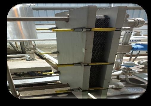
Fig.1 Plate Type Heat Exchanger
Fromfigno.1platetypeheatexchangerusetodecrease temperatureofcoolingtowerfeedwater.Makeofplate type heat exchanger Kelvion India Pvt. Ltd. Having model, no :NT80M V-22PL. Design pressure of this exchanger is up to 10Bars. It can sustain temperature upto100°C.
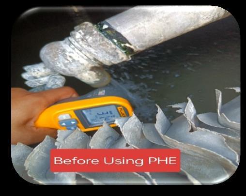
Fig.2 Temperature reading of water before using PHE
International Research Journal of Engineering and Technology (IRJET) e-ISSN: 2395-0056
Volume: 13 Issue: 05 | May 2026 www.irjet.net p-ISSN: 2395-0072
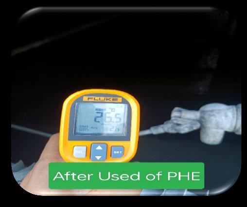
Fig.3 Temperature reading of water after using PHE
Inabovefigureno.3aswecheckedtemperatureofwater readingbyFlukemakeinfraredthermometer.After installingPHEweobservedthetemperatureofsumpupto 26.5°C.BeforeinstallingPHEtofeedwatertemperature was31.5°C.whichishotforcondensercomparedto26.5°C.
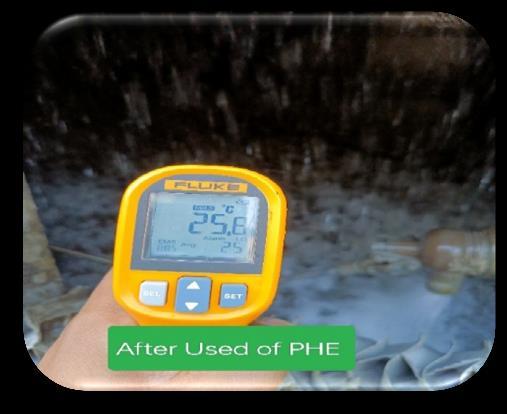
Fig.4 Temperature reading of water in the running condition of condenser
As shown in above figure no.4 we get a temperature reading 25.6°C in running condition of evaporative condenserandcoolingtower.
Intothisplatetypeheatexchanger,wegivenhotwaterata temperatureinrangeof30°Cto32°Cwhichisweareusing itdirectlytothecondenserfeedintheprevioustimebefore completion of project and other side cold temperature is used at 10°C to 13°C which comes from the whey RO generationfromplant.
TheheatloadcalculationafterinstallingPHEisasfollows:
Thi = Temperature of hot fluid entering the heat exchanger in°C(31°C)
Tho =Temperatureofhotfluidoutoftheheatexchangerin °C(27°C)
Tci =Temperatureofcoldfluidenteringtheheatexchanger in(10°C)
Tco =Temperatureofcoldfluidoutoftheheatexchangerin °C(14°C)
Logmeantemperaturedifference
ΔTLMTD = [ ] = [ ] =0/0
Temp.Differenceis17°C
Areaofplatetypeheatexchangeris,[8]
Length=1150mm=1.15m
Width=570mm=0.570m
Thicknessofplate=0.5mm=0.005m
A=(N-1)XAplate
Where, N = Number of plates of plate type heat exchanger
A=Areaofplate
A=(21-1)x(0.570x1.15)
A=13.11m2
So, the total area covered by the heat exchanger is 13.11m2
HeatTransferRate:[9]
Q=UxAxΔTLMTD
Where, U = Overall heat transfer coefficient in kcal/hr m2°C
A=Heattransfersurfaceareinm2
Q=Rateofheattransferbetweentwofluidsinkcal/hr
ΔTLMTD =Logmeantemperaturedifferencein°C
Q=3440.06x13.11x17 =766686.17kcal/hr. =891.058kW.
Here,heatfromthehotfluidatarateof891.058kWis transferredtoobtainwateratatemperatureof27°C. AfterfittedPHEparametersarechangedasperbelow:
Condensersump=27.24˚C
Condensersump2=25˚C
Condensersump3=26˚C
Condensersump4=26.8˚C
Condensersump5=27˚C
CondenserliquidHeadertemperature=36.5˚C
Wetbulbtemperature=25˚C
AverageHumidityofyear2024(RH)=48.75%
Range is the difference between the cooling tower waterinletandoutlettemperature
Range=Tout−Tin
Ifthewaterentersat27.8°Candexitsat23.61°C,then: Range=27.8–23.61=4.19°C
Approach is the difference between the cooling tower outlet cold water temperature and ambient wet bulb temperature. Although, both range and approach
International Research Journal of Engineering and Technology (IRJET) e-ISSN: 2395-0056
Volume: 13 Issue: 05 | May 2026 www.irjet.net p-ISSN: 2395-0072
shouldbemonitored,the‘Approach’isabetterindicatorof coolingtowerperformance.[14].
Approach=Tout Twet bulb Using the mean yearly wet-bulb temperatureofRanjangaonregion25°C
Approach=27.8−25=2.8°C
Cooling tower effectiveness (in percentage) is the ratio of range to the ideal range, i.e. difference between cooling waterinlettemperatureandambientwetbulbtemperature
CoolingTowereffectivenessin%= x100%
= x100
=59.9%
Coolingcapacityistheheatrejectedinkcal/hrorTR,Given as product of mass flow rate of water, specific heat and temperaturedifference.
Coolingtowerflow/Cell=225m3/hr.
Cooling Duty Handled/Cell in kcal = Cooling tower flow/Cellx (Tout–Tin)x1000 =225x(27.8–23.61)x1000 =942750kcal/hr.
Evaporation Loss = 0.00085 x 1.8 x Circulation ratio(m3/hr.)x(Tout–Tin)
=0.00085x1.8x225x(27.8–23.61) =1.44m3/hr.perCellorCondenser
Percentage Losses = [ Evaporation Loss / Cooling tower flow/Cellinm3/hr.]x100 =[1.44/225]X100 =0.641%
Cycle of Concentration (COC) = TDS of Circulating water / TDSofMakeupwater =2120/113 =18.76
BlowdownrequirementforsiteCOCof30.97=Evaporation Loss/(COC-1) =1.44/(18.76-1) =0.081m3/hr.
Makeup water requirement/cell in m3 /hr. = Evaporation Loss+BlowdownLoss =1.44+0.081 =1.521m3/hr.
HeatRejected=[McxCp x(To –Ti)]/3024
Mc=MassflowrateofcoolingwaterinKg/hr.
Cp =Specificheatofwateratkcal/kg°C.
Ti =Coolingwatertemperatureatcondenserinletin°C.
To=Coolingwatertemperatureatcondenseroutletin°C.
Cp =1.0kcal/kgat27°C
Mc=225000kg/hr
Ti =23.61°C.
To=27.8°C.
HeatRejected=[225000x1.0x(27.8–23.61)]/3024 =942750/3024 =311.75TR
Difference between previous and current evaporation lossesandheatrejectedareasfollows:
Evaporation losses before installing PHE and ETP RO Project,
Difference in evaporation loss = Before Project- After Project = (3.786 – 1.44) m3/hr. per cell or condenser =2.346m3/hr percellorcondenser We saved water consumption 2.346 m3/hr per cell or condenser
Percentage losses before installing PHE and ETP RO Project,
Difference in percentage losses = Before Project- After Project = (1.683- 0.641) % per cell or condenser =1.042%percellorcondenser
UseofROwaterinevaporativecondenserssignificantly improvedenergyefficiencyandreducedmakeupwater consumption by2.501m3/hr percell orcondenserand cooling towers, making the refrigeration plant more cost-effective and environmentally sustainable. Water Quality Stabilized Sludge removal, biological cleaning, and visual inspection of water condition led to improved clarity, reduced microbial growth, and minimized chemical dosing losses. Mechanical Reliability Enhanced Inspection and identification of corrodedcomponents(e.g.,fanshafts,structure)enable proactive maintenance, extend equipment life, and reduce unexpected shutdowns. Chemical consumption reduces&costofchemicalsavesduetopH maintained in range 8 to 9 & TDS maintain in sump water 10 –2500ppm. Percentage of Hydrogen Ions (pH), Total Dissolved Solids (TDS), and Biological Oxygen Demand (BOD) meters will be installed on the condenser water sump to monitor the water parameters and automatically perform water blowdown from the condensersump.
Table 8: Comparison table on parameters before and after completion of the project
Theoretical Parameters Before Project After Project
©2026, IRJET | Impact Factor value: 8.315 | ISO 9001:2008
International Research Journal of Engineering and Technology (IRJET) e-ISSN: 2395-0056
Volume: 13 Issue: 05 | May 2026 www.irjet.net p-ISSN: 2395-0072
11. https://www.weatheratlas.com/en/india/ranjangaon-weather-march
1. B. Kiran Naik, P. Muthukumar, "Performance Investigations of a Cross-Flow Cooling Tower," International Journal of Scientific & Engineering Research,Vol.e4(12),2013,pp68-73.
2. K. A. Manske, D.T.Reindl, S.A.Klein, “Evaporative condenser control in industrial refrigeration systems”, International Journal of Refrigeration, vol 24, 2001, pp 676-691.
3. Janusz Pospolita , Anna Kuczuk, Katarzyna Widera, Zbigniew Buryn, Robert Cholewa, Andrzej Drajczyk, Mirosław Pietrucha, Rafał Smejda, "Water Losses in Condenser Cooling Systems," energies MDPI, vol. 15, 2022,pp1-25.
4. Mr. N.Thiru Senthil Adhiban, M.Sukel Ahamed, S.Sugumar, P.Nethaji, "Performance Analysis And Efficiency Improvement of Cooling Tower At Mtps-I, International Research Journal of Engineering and Technology(IRJET),vol.9(6),2022,pp378-384.
5. E Habibur Rahman, Altab Hossain, Mohammad Ali, “Experimental investigation on cooling tower performance with Al2O3,ZnO and Ti2O3 based nanofluid”,AIMSMaterialsScience,vol.11(5),2024,pp 935-949.
6. J. Dixon Jim Joseph, K. Rajan Chakravarthi, M. Sarathkumar, V. Sharan Raghul, M. Vijay Kumar, “AnalysisonPerformanceofCondenserinThermall
7. Power Plant”, International Journal of Engineering Research&Technology(IJERT),vol5(7),2017,pp1-4.
8. Boiler Operation Engineering Book, Chapter Cooling watertreatmentandCoolingtower,pg.no.589to653.
9. Arora Domkundwar, A Course in Power plant engineering, -DHANAPAT RAI & CO. chapter name coolingpondsandcoolingtowerpg.no18.1to18.40.
10. BureauofEnergyEfficiencybook(3rd)pageno.204


Mr. Aniket S. Kadekar is a Student of a Mtech in Heat Power Engineering , Department of Mechanical Engineering,GHRaisoniCollege of Engineering and Management, Pune, Maharashtra,India

Dr.Dipak S. Patil is working as Professr, Department of Mechanical Engineering, G H Raisoni College of Engineering and Management, Pune, Maharashtra,India