
International Research Journal of Engineering and Technology (IRJET) e-ISSN: 2395-0056
Volume: 13 Issue: 04 | Apr 2026 www.irjet.net p-ISSN: 2395-0072
International Research Journal of Engineering and Technology (IRJET) e-ISSN: 2395-0056
Volume: 13 Issue: 04 | Apr 2026 www.irjet.net p-ISSN: 2395-0072
T.
Surya Aparna1, M. Mamatha Devi2, A. Sravika3, K. Divya4, M. Monaksha Abhinay5 , Punnam Nagaraju6
12345 B.Tech Students , 6Assistant Professor, Department of Electronics and Communication Technology, Sri Vasavi Engineering College, Tadepalligudem, Andhra Pradesh, India
Abstract - In this paper, a half-mode substrate integrated waveguide (HMSIW)-based bandpass filter (BPF) with a hollow bowtie-shaped spoof surface plasmon polariton (SSPP) structure is proposed. In the proposed design, the lower cut-off frequency is primarily determined by the HMSIW dimensions, while the upper cut-off frequency is effectively regulated by the hollow bowtie-shaped SSPP grooves. With a center frequency of 7.45 GHz and FBW of 51.3%, the filter operates from 5.54 to 9.36 GHz. It achieves a stopband rejection over 42.5 dB from 9.76 GHz to 14.42 GHz, a return loss greater than 12 dB across the passband, and an insertion loss of 0.34 dB at the center frequency (fc). The proposed BPF’s overall size of 0.72λg × 2.32λg, makes it ideal for C- and X-band wireless applications.
Key Words: Half-mode substrate integrated waveguide, hollow bowtie-shaped spoof surface plasmon polaritons, bandpass filter and compact design.
Inmodernmicrowaveandmillimeter-wavecommunication systems, filters play a crucial role by allowing desired frequenciestopasswhileblockingunwantedandinterfering signalsimprovingsignalintegrityandtheperformanceofan overallsysteminvariousapplicationssuchasradar,satellite communications,andhigh-frequencywirelesssystems.[1]. The spoof surface plasmon polaritons (SSPPs) are widely used in modern microstrip implementations to improve selectivity,reducesize,andincreaseout-of-bandrejection [2].Amongallthesemicrowavefilters,band-passfiltersare crucialtomodernwirelesscommunicationsystemsbecause they allow only the desired frequency band to pass while rejectingundesiredsignals[3].Manytechnologiessuchas metallic waveguides, coplanar waveguides (CPW), microstrip lines, coupled-line topologies, slot-based structures,andSubstrateIntegratedWaveguide(SIW)are used to implement Microwave filters. Among these many technologies,metallicwaveguidesrequiredifferentdesign considerations in terms of size, selectivity, insertion loss, difficultyintegratingwithplanarcircuits,andoverallsystem performance [4]. The SIW technology was introduced to address the limitations which effectively simulate the behaviorofaconventionalrectangularwaveguidebyusing twoparallelrowsofmetallicviasinadielectricsubstrate[5]. ThedesignequationsandoperationalcharacteristicsofSIW, including the calculations of effective widths, lengths, and
cut-offfrequencieswereprovidedbyrecentresearchinthis field [6] and [7], which provides an extensive analytical frameworkforSIW-basedmicrowavecomponentdesign.By successfullyintegratingSSPPandSIWincompactmodern microwave filtering applications, recent hybrid SIW–SSPP bandpass filter designs have demonstrated enhanced performance by achieving wider bandwidth, improved selectivity, and superior out-of-band rejection [8]. The HMSIWcanbecreatedfromatraditionalSIWbydividingit in half through one of its magnetic walls, to achieve reduction in size and enhance integration with planar circuits, which will typically provide a reduction in the component's size of about 50% [9]. The dumbbell-shaped SSPPisintegratedintoaSIWstructure.Inadditiontobeing compact,thecarefullydesignedhybridstructureachievesa highlevelofmountingsuppression[10].Thegroovedepth controls the cutoff frequency and field confinement of the SSPP structure. SSPP structures provide strong electromagneticconfinementandcompactsize,whileSIW offerslowlossandgoodpowerhandlingcapability[11].By combining the advantagesofboth structures,hybridSIWSSPP technology offers an effective method for realizing compactandhigh-performancemicrowaveandmillimeterwavecomponents[12].ThehybridHMSIW‑SSPPslow‑wave structureapproachsuccessfullycreatesband‑passbehavior withreducedsizeandstrongconfinementwhileimproving effective electrical length without increasing physical size [13].Byadjustingthedispersioncharacteristicsofperiodic structures,compactSSPP-basedbandpassfiltershavebeen developedtoachievewidebandwidthalongwithenhanced upper-band rejection [14]. Natural surface plasmon polaritons(SPPs)arelimitedtoopticalfrequenciesdueto the negative permittivity of metals. At microwave frequencies, metals act as ideal electric conductors, preventingthenaturalspreadofSPP.SpoofSurfacePlasmon Polaritons(SSPPs) areused toovercomethisissue.SSPPs areenabledby engineered periodic structuresonmetallic surfaces that enable SPP-like wave propagation at microwavefrequencies[15].
Inthiswork,acompacthybridHMSIW-SSPPBPFintegrated withahollowbowtie-typeSSPPgeometryisproposed.The uppercutofffrequencyiseffectivelycontrolledbythehollow bowtie-shaped SSPP geometry, resulting in an enhanced wideband BPF response and improved selectivity. This configuration supports SSPP propagation and enables flexiblefrequencytuningprimarilythroughtheouterbowtie length(b1)andinnerbowtielength(b2).Byappropriately
International Research Journal of Engineering and Technology (IRJET) e-ISSN: 2395-0056
Volume: 13 Issue: 04 | Apr 2026 www.irjet.net p-ISSN: 2395-0072
adjustingthese parameters, animprovedandcontrollable frequency response is obtained. A comprehensive parametric analysis is carried out to guide the design process.Theproposedfilterexhibitsenhancedcompactness, sharp selectivity, strong stopband suppression, and improvedinsertionandreturnlosscharacteristics,makingit a promising candidate for C-band and X-band wireless communicationapplications.
2.1 Design of standard HMSIW structure
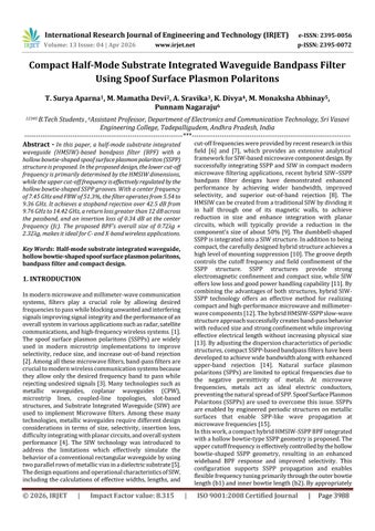
Thedesignprocessbeginswiththedesignofastandard HMSIWasshowninFig.1.
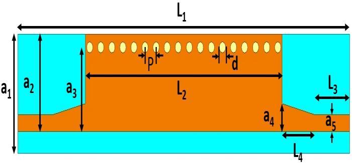
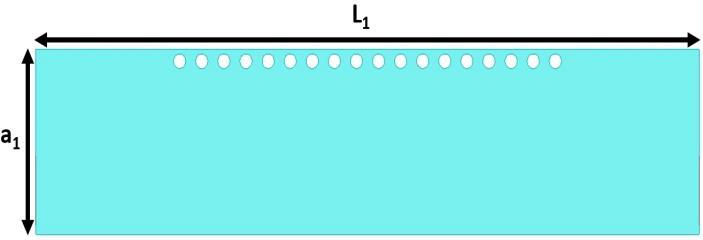
Fig. 1. ThestructureoftheHMSIWfilter(a)topview(b) bottomview
The electrical characteristics of the SIW structure are comparable to those of a standard rectangular waveguide. The key design parameters, including the effective width, length, and cutoff frequency, are determined using the followingequations(1),(2),and(3)in[6]and[7].



Equations(1),(2),and(3),aeff andLeffindicatesthatthe effective width and length of the SIW. While aSIW and LSIW represents the physical width and length of the SIW, c denotes the velocity of light in free space, d indicates the diameterofthemetallicviaholes,andpdefinestheperiodic
interval between vias. Substrate width a1, patch width a2, effectivewidtha3,taperedtransitionwidtha4,feedwidtha5, substrate length L1, patch length L2, feed length L3, and taperedtransitionlengthL4 arethephysicalvariablesofthe HMSIWfilter.Thefilter’soptimumgeometricalparametersof the filter are a1=12.5 mm, a2=10.5 mm, a3=9.7 mm, a4=2.8 mm,a5=2mm,p=1.8mm,L1=54mm,L2=32mm,L3=6.65mm, L4=4.35 mm, and d=1 mm. The simulated S-parameter responseoftheHMSIWfilterisillustratedinFig.2.Itshows thattheoperatingfrequencyofHMSIWat5.54GHzexhibits goodreturnlossandlowinsertionloss.
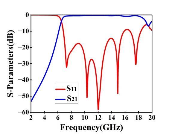
Fig. 2. SimulatedoutputoftheHMSIWfilter
The effect of HMSIW width (a₃) on the filter response is analyzed,asshowninFig.3.Itisobservedthata₃ismostly controls the lower cutoff frequency. The lower cut-off frequencyshiftstowardlowerfrequencieswhena₃increases from 8.7 mm to 10.7 mm. For instance, the lower cutoff frequencyisconsideredata₃=9.7mm.Meanwhile,theupper cutoff frequency remains nearly unchanged. Therefore, HMSIWwidthisanimportantparameterforindependently adjustingtuning
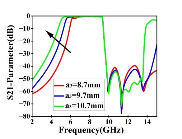
Fig.3.Simulatedoutputfordifferentvaluesof a3
2.2 Design Methodology of the Proposed HMSIW–SSPPBased BPF
To achieve bandpass characteristics in the C- and X-band frequencyranges,theproposedcompactmicrowaveBPFis designedbycombiningbothHMSIWandSSPPunits,whichis realized by integrating hollow bowtie-shaped SSPP structuresintotheHMSIWconfiguration,asplottedinFig.4.
International Research Journal of Engineering and Technology (IRJET) e-ISSN: 2395-0056
Volume: 13 Issue: 04 | Apr 2026 www.irjet.net p-ISSN: 2395-0072
Theintegrationofhollowbowtie-shapedSSPPelementsinto the conventional HMSIW filter results in a bandpass response because both HMSIW and SSPP structures are knowntoexhibithigh-passandlow-passcharacteristics.
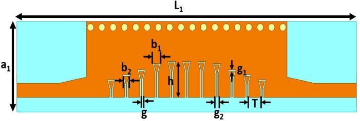
Fig. 4. LayoutofproposedHMSIW-SSPPbandpassfilter (a)Topview(b)Bottomview
The slow-wave effect is achieved by integrating subwavelength periodic SSPP structures onto the HMSIW’s uppersurface.AsshownintheFig.4,thephysicalvariables of the proposed hollow bowtie-shaped SSPP elements are outerbowtielengthb1,innerbowtielengthb2,heightofSSPP h,widthoftherectangularSSPPslotg,innerspacingofthe bowtie-shapedslotg1,spacingbetweenadjacentrectangular slotsg2,andspacingbetweenSSPPunitcellsT.Thefilter’s optimized geometrical parameters of the filter are b1=1.2 mm,b-=0.82mm,h=4.96mm,g=0.2mm,g1=0.2mm,g2=0.52 mm,T=1.88mm.
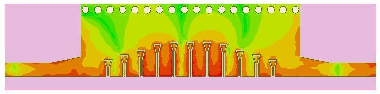
ThefieldpropagationacrossthecompacthybridHMSIW–SSPP BPF with a hollow bowtie-type SSPP geometry at centerfrequency7.45GHzasshowninFig.5.Itisevident that the electric field is tightly confined within the SSPP units, with confirming effective field confinement and localization.Theimpactofbowtiestructuraldimensionson the frequency response filter was evaluated by the parametricstudiesasillustratedinFig.6.Itshows,heightof SSPP(h),theouterbowtielength(b1),innerbowtielength (b2),offersignificantdesignflexibilitytoadjustpassband’s upper cutoff frequency. The S21 parameters shows that whentheinnerbowtielength(b2)from0.72mmto0.92mm, the upper cut-off frequency value to shift downward as
shown in Fig.6 (b). The parametric analysis also indicates that,whereasb1andhhaveasignificantimpactontheupper limit of the passband, variations in b2 provide a more moderateeffectasshowninFig.6,whichmakesitanideal parameterforthefine-tuningthefilterresponse.
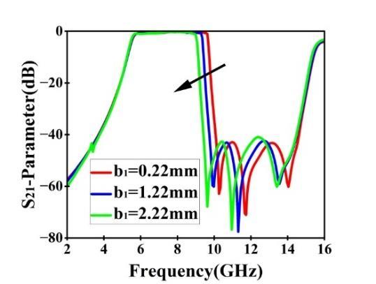
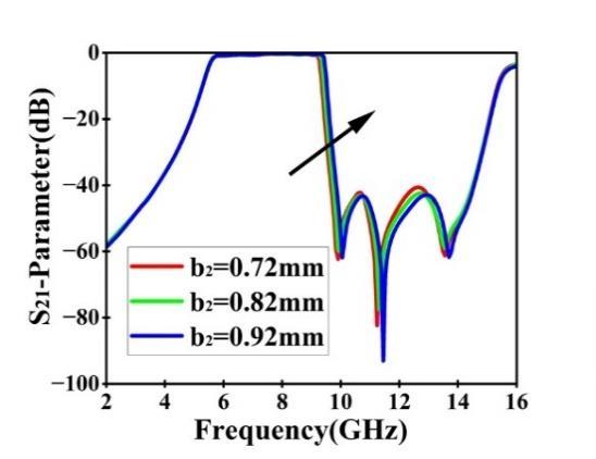
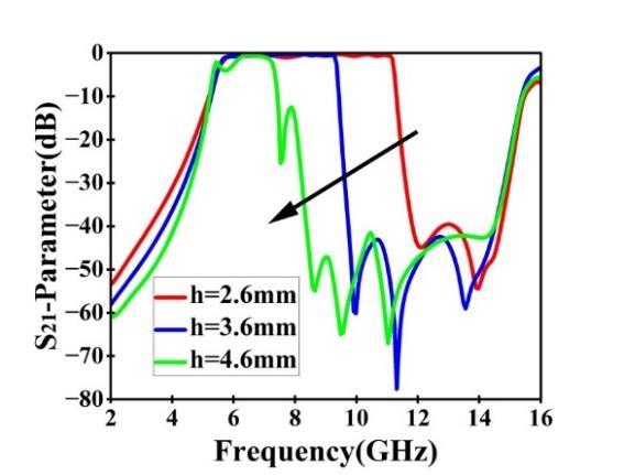
Fig. 6. Simulatedoutputundervariationsin(a)b1 (b)b2 (c)h
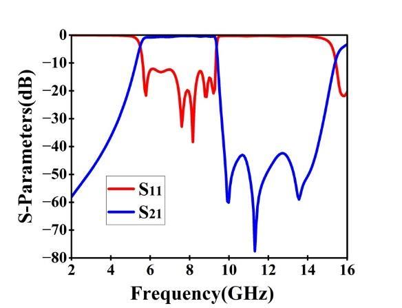
Thesimulatedoutputoftheproposedfilterisillustratedin Fig.7.Thefilterexhibitsapassbandfrom5.54GHzto9.36 GHzwithacenterfrequencyof7.45GHz.Thehigher-order modesmaybecomeslightlyactiveinanHMSIW-SSPP-based filterjustbeyondthepassbandregion.
International Research
Volume: 13 Issue: 04 | Apr 2026 www.irjet.net p-ISSN: 2395-0072
3. Results and Discussion
The proposed HMSIW-SSPP based BPF shows a passband from 5.54 GHz to 9.36 GHz with an FBW of 51.3%. The insertion loss is approximately 0.34 dB at the center frequencyandremainswithin0.73dBacrossthepassband, andthereturnlossisbetterthan12.5dBacrosstheentire passband.Inaddition,asuppressionlevelofmorethan42.5 dB is observed from 9.76 GHz to 14.42 GHz, indicating effectivestopbandperformance,andsignificantattenuation outsidethepassband.Theproposedfilteroverallsizeis0.72 λg×2.32λg,whereλgistheguidewavelength.Theproposed BPF performance is compared with a few published SSPP basedBPFsastabulatedinTableI.Thecomparisonclearly highlights that the proposed filter offers significant improvementsintermsofsizeandinsertionloss.
Table -1: ComparisonofProposedHMSIW–SSPP BandpassFilterwithExistingDesigns

AcompactHMSIW-basedbandpassfilterintegratedwitha hollowbowtie-shapedSSPPstructurehasbeensuccessfully presented.Theproposedstructureeffectivelycombinesthe advantages of HMSIW and SSPP technologies, where the lower cutoff frequency is primarily determined by the HMSIW dimensions and the upper cut-off frequency is effectively regulated by the hollow bowtie-shaped SSPP grooves.Inparticular,thekeystructuralparametersofthe hollow bowtie-shaped SSPP, b₁ and b₂, can be changed to further adjust the upper cutoff frequency. The hollow bowtie-shapedSSPPdesigneffectivelyovercomingspacing constraintswhileachievingimprovedinsertionandreturn lossperformance.Withafractionalbandwidthof51.3%,low insertion loss, and good return loss across the operating band,theproposedfilterprovideswidebandperformance.In addition,strongout-of-bandsuppressionexceeding42.5dB highlights its excellent selectivity. With its compact size, wide bandwidth, and excellent frequency response, the proposedfilterisapromisingcandidateformodernC-and X-bandapplications.
[1] A.Rahimian,“Modellingandperformanceofmicrowave and millimetre-wave layered waveguide filters,” TELKOMNIKA,vol.11,no.7,pp.3523–3533,Jul.2013.M. Young, The Technical Writer’s Handbook. Mill Valley, CA:UniversityScience,1989.
[2] L.Yang,H.Liu,B.Cai,L.Wu,andY.Cheng,“Miniaturized broadband high out-of-band rejection bandpass filter based on spoof surface plasmon polaritons with defectedgroundstructure,”ScientificReports,vol.14, Art.no.26722,2024.
[3] S.GruszczynskiandK.Wincza,“Novelsynthesismethod for microwave parallel-coupled resonator bandpass filters,”Electronics,vol.14,no.15,p.3123,Aug.2025.
[4] M.-A.Chung,C.-W.Lin,andY.-H.Chen,"Acompactand low-loss microstrip filtered power divider for millimetre-wave applications," IEEE Access, 2025, DOI:10.1109/ACCESS.2025.3606458.
[5] L. Ye, Y. Chen, K. D. Xu, W. Li, Q. H. Liu, and Y. Zhang, “Substrate integrated plasmonic waveguide for microwave bandpass filter applications,” IEEE Access, vol. 7, pp. 75957–75964, 2019, doi: 10.1109/ACCESS.2019.2920925.
[6] H. Hao, D. Wang, and Z. Wang, “Design of substrateintegratedwaveguideloadingmultiplecomplementary open resonant rings (CSRRs) for dielectric constant measurement,”Sensors,vol.20,no.3,p.857,Feb.2020, DOI:10.3390/s20030857.
International Research Journal of Engineering and Technology (IRJET) e-ISSN: 2395-0056
Volume: 13 Issue: 04 | Apr 2026 www.irjet.net p-ISSN: 2395-0072
[7] D.Pan,B.You,X.Wen,and X.Li,“Widebandsubstrate integrated waveguide chip filter using spoof surface plasmon polariton,” Micromachines, vol. 13, no. 8, p. 1195,Jul.2022,DOI:10.3390/mi13081195.
[8] P.Chen,L.Li,K.Yang,andQ.Chen,“Hybridspoofsurface plasmonpolaritonandsubstrateintegratedwaveguide broadband bandpass filter with wide out-of-band rejection,”IEEEMicrowaveandWirelessComponents Letters,vol.28,no.11,pp.984–986,Nov.2018.
[9] L.Zhao,Y.Li,Z.-M.Chen,X.-H.Liang,J. Wang, X.Shen, and Q. Zhang, “A band-pass filter based on half-mode substrate integrated waveguide and spoof surface plasmonpolaritons,” ScientificReports,vol.9,Art.no. 13429,2019
[10] R. S. Sangam and R. S. Kshetrimayum, “Hybrid spoof surface plasmon polariton and substrate integrated waveguide bandpass filter with high out-of-band rejection for X-band applications,” IET Microwaves, Antennas & Propagation, vol. 15, no. 3, pp. 289–299, 2021.
[11] B. Zhang et al., "Narrowband SIW-SSPP hybrid bandpassfilterwithcompactprofileatKa-band,"IEEE Access,2023,DOI:10.1109/ACCESS.2023.3312288
[12] Y.Liuetal.,"Compactslow-wavehalf-modesubstrate integrated waveguide with spoof surface plasmon polaritons for miniaturized microwave circuits," IEEE Access,2024,DOI:10.1109/ACCESS.2024.3425834
[13] L.Tan,Q.Wang,Y.-J.Guo,J.Cui,andK.-D.Xu,“Bandpass filterbasedonspoofsurfaceplasmonpolaritonswitha switchable high-selectivity notch band,” Frontiers in Physics,vol.9,Art.no.754510,Aug.2021.
[14] D. Zhang, K. Zhang, Q. Wu, and T. Jiang, "A Compact Wideband Filter Based on Spoof Surface Plasmon Polaritons with a Wide Upper Rejection Band," IEEE PhotonicsTechnologyLetters,vol.32,no.23,pp.14771480,Dec.2020.
[15] J. B. Pendry, L. Martín-Moreno, and F. J. García-Vidal, "MimickingSurfacePlasmonswithStructuredSurfaces," Science,vol.305,no.5685,pp.847-848,2004.