
International Research Journal of Engineering and Technology (IRJET) e-ISSN: 2395-0056
Volume: 13 Issue: 04 | Apr 2026 www.irjet.net p-ISSN: 2395-0072
International Research Journal of Engineering and Technology (IRJET) e-ISSN: 2395-0056
Volume: 13 Issue: 04 | Apr 2026 www.irjet.net p-ISSN: 2395-0072
Vinesh P1, Tharun M2 , Sujan R3, Mohammed Raashidh S4, Dr. G. Suresh Kannan5
1,2,3,4 B. E Mechanical Engineering, Coimbatore Institute of Technology, Coimbatore, India
5 Associate Professor, Dept of Mechanical Engineering, Coimbatore Institute of Technology, Coimbatore, India
Abstract - In contemporary engineering industries, particularlyinsectorssuchasoilandgas,petrochemicals, and energy production, the efficiency of project execution is highly dependent on the accuracy and consistency of digitalengineeringdata.Pipingengineering,beingacritical component of plant design, involves extensive interaction between design tools, material databases, and interface files. One of the major challenges encountered in such environments is the inconsistency of commodity codes acrossdifferentdatasets,leadingtodiscrepanciesinSmart 3D(S3D)modelsandassociatedengineeringworkflows. Thisstudypresentsacomprehensiveautomationapproach aimed at addressing these inconsistencies through the development of customized tools using Visual Basic for Applications (VBA) and C#. The primary tool focuses on comparing specification identification sheets to detect changes in commodity codes and extract relevant differences such as skipped, added, modified, and deleted components. A graphical user interface (GUI) developed usingC#enhancesusabilityandensureseaseofoperation. Additionally,asecondaryautomationtoolisintroducedto streamline the tagging process in orthographic diagrams. This tool simplifies complex tag structures by converting them into sequential identifiers while maintaining traceabilitythroughmappingfiles. Theimplementationofthesetoolsdemonstratessignificant improvements in efficiency, accuracy, and workflow integration. The results highlight the potential of automation in reducing manual effort, minimizing errors, andenhancingcoordinationacrossengineeringteams.
Piping engineering plays a crucial role in the design and operation of industrial plants, particularly in sectors such as oil and gas, petrochemical, power generation, and process industries. These systems are responsible for transporting fluids such as liquids, gases, and slurries under controlled conditions. The reliability, safety, and efficiency of these systems depend on precise design, accurate data management, and seamless coordination betweenmultipleengineeringdisciplines. Inrecentyears,theadoptionofdigitalengineeringtoolshas significantly transformed the way piping systems are designedandmanaged.Advancedsoftwareplatformssuch asSmart3DandSmartPlantMaterialsenableengineersto
create highly detailed 3D models, manage large datasets, andensurecompliancewithinternationalstandards.These tools integrate geometry, material specifications, and engineeringdataintoaunifiedenvironment. However,despitethesetechnologicaladvancements,oneof the major challenges in modern piping engineering is maintaining data consistency across multiple systems. Engineering data is typically distributed across various interface files such as specification sheets, catalogue workbooks, and generic data files. These files are interconnected, and any inconsistency between them can leadtosignificantissuesinthedesignprocess.
A critical element within these datasets is the commodity code, which uniquely identifies each piping component. When updates occur in catalogue data without proper synchronization, components may lose their reference in thesystem.Thisresultsinmissingelementsin3Dmodels, incorrect material specifications, and increased manual verificationefforts.
To overcome these challenges, automation becomes essential.Byimplementingautomatedtools,engineerscan reduce manual effort, improve accuracy, and enhance overallproductivity.Thisstudyfocusesondevelopingsuch automation tools using VBA and C# to streamline data comparison and simplify tagging systems in piping engineeringworkflows.
The engineering industry is undergoing a significant transformation driven by digitalization. Traditional methodsofdesign,whichreliedheavilyonmanualdrafting andisolateddatasystems,arebeingreplacedbyintegrated digital platforms that enable real-time collaboration and datasharing.
Digital engineering involves the use of advanced software tools, data analytics, and automation technologies to improve the efficiency and accuracy of engineering processes.Inpipingengineering,thisincludestheuseof3D modeling tools, database management systems, and automatedworkflows.
One of the key advantages of digital engineering is the abilitytohandle large volumesofdata efficiently.Modern projects involve thousands of components, each with
International Research Journal of Engineering and Technology (IRJET) e-ISSN: 2395-0056
Volume: 13 Issue: 04 | Apr 2026 www.irjet.net p-ISSN: 2395-0072
detailedspecifications.Managingthisdatamanuallyisnot feasible,whichmakesautomationanecessity. Another important aspect is interoperability between different software systems. Tools like Smart 3D and AutoCAD Plant 3D must work together seamlessly to ensureconsistencyacrossdesignandmaterialdata. Despite these advancements, challenges such as data inconsistency,duplication,andsynchronizationerrorsstill exist. These issues highlight the need for intelligent automation solutions that can bridge the gap between differentsystemsandensurereliabledataflow.
Piping engineering is a multidisciplinary field that combines principles of mechanical engineering, fluid mechanics, thermodynamics, and materials science. The primary objective of piping engineering is to design systems that can safely and efficiently transport fluids undervariousoperatingconditions.
3.1ComponentsofaPipingSystem
A piping system consists of several components, each servingaspecificfunction:
• Pipes: These are the primary elements used to transport fluids. They are selected based on material,diameter,andthickness.
• Valves:Usedtocontroltheflowoffluidwithinthe system. Different types include gate valves, globe valves,andballvalves.
• Flanges:Provide detachableconnectionsbetween pipesandequipment.
• Gaskets: Ensure leak-proof connections between flanges.
• Fittings: Used to change the direction or size of pipes(elbows,tees,reducers).
• Supports:Providestructuralstabilitytothepiping system.
3.2DesignConsiderations
Designingapipingsystemrequirescarefulconsiderationof severalfactors:
• Pressure and Temperature: The system must withstandoperatingconditionswithoutfailure.
• Fluid Properties: Corrosive or hazardous fluids requirespecialmaterials.
• Thermal Expansion: Pipes expand and contract withtemperaturechanges.
• Safety Standards: Compliance with standards ensuresreliability.
3.3CodesandStandards
Piping systems are designed according to international standardssuchas:
• ASMEB31.3(ProcessPiping)
• ASMEB31.1(PowerPiping)
These standards define guidelines for design, materials, testing,andsafety.
4. PROBLEM STATEMENT
One of the major challenges in piping engineering is the inconsistency of data across multiple systems. This issue arisesduetofrequentupdatesincataloguedata,whichmay notbeproperlysynchronizedwithdesignmodels.
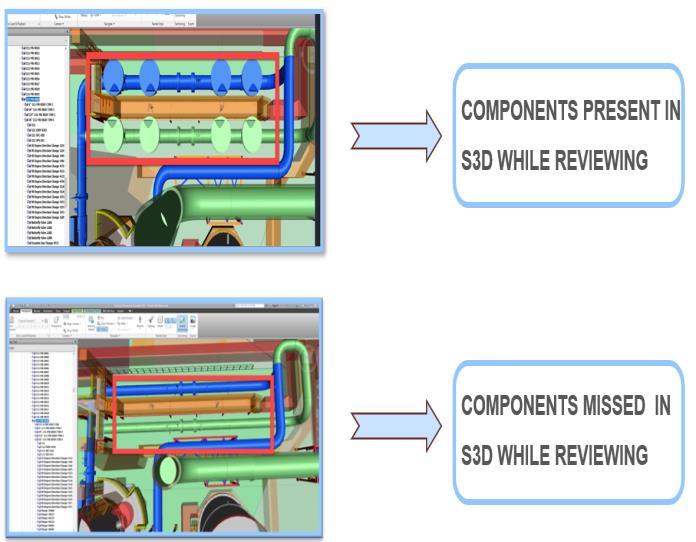
-1:Componentspresentvs.missinginS3Ddueto commoditycodemismatch
Commodity codes serve as unique identifiers for components.Whenthesecodesareupdated:
• Existingcomponentslosetheirreference
• Modelsshowmissingelements
• Engineers must manually identify and correct errors
Thisprocessistime-consumingandpronetomistakes.
4.2ManualComparisonProblem
Engineers often rely on manual methods such as Excel comparison to identify differences between datasets. This involves:
• Comparingthousandsofrows
• Identifyingmismatches
• Extractingrelevantdata
Thisapproachisinefficientandnotscalable.
4.3TaggingComplexity
Orthographic diagrams use long tags that are difficult to interpret. This creates communication issues between teamsandincreasesthelikelihoodoferrors.
International Research Journal of Engineering and Technology (IRJET) e-ISSN: 2395-0056
Volume: 13 Issue: 04 | Apr 2026 www.irjet.net p-ISSN: 2395-0072
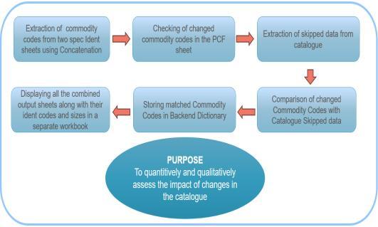
Fig-2:Proposedmethodologyflowchartfor commoditycodeautomation
5.1CommodityCodeAutomationTool
Theautomationprocessconsistsofmultiplestages:
5.1.1DataPreparation
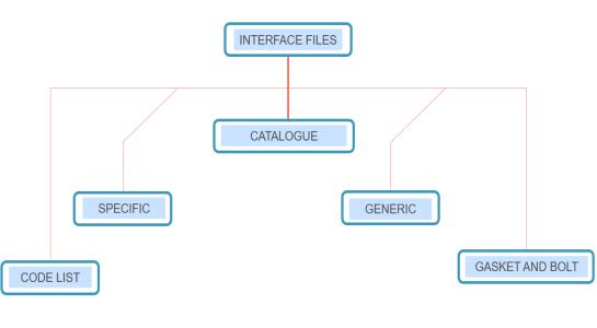
Fig-3:HierarchyofS3Dinterfacefiles
Inputfilesinclude:
• Previousspecidentsheet
• Updatedspecidentsheet
• Catalogueworkbook
Thesefilesareloadedintothesystemforprocessing.
5.1.2ConcatenationLogic
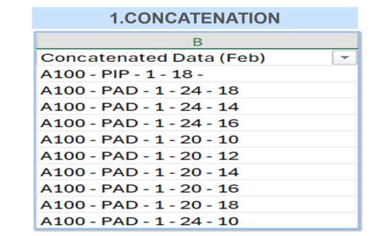
Fig-4:UniquekeygenerationusingconcatenationofSpec Code,ShortCode,Option,andSize
To uniquely identify components, multiple fields are combined:
• ShortCode
• OptionCode
• Sizeparameters
Thiscreatesauniquekeyforcomparison.
5.1.3ComparisonAlgorithm
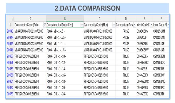
Fig-5:DatacomparisonoutputbetweenFebruaryand Marchdatasets
Thealgorithmcomparesdatasetsandidentifies:
• Matchingentries
• Mismatchedentries
• Missingentries
This is done using VBA loops and dictionary-based matching.
5.1.4ExtractionProcess
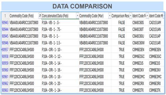
Fig-6:PCFMethodStep1 Extractionofpiping commodityfilterdata
Thesystemextracts:
• Skippedcomponents
• Modifiedcomponents
• Addedcomponents
• Deletedcomponents
Eachcategoryisstoredinaseparateworksheet.
International Research Journal of Engineering and Technology (IRJET) e-ISSN: 2395-0056
Volume: 13 Issue: 04 | Apr 2026 www.irjet.net p-ISSN: 2395-0072
5.1.5GUIDevelopment
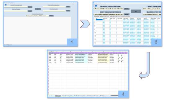
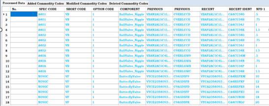
Fig-7:FinaloutputdisplayedintheC#graphicaluser interface
Auser-friendlyinterfaceisdevelopedusingC#:
• Fileselectionbuttons
• Executioncontrols
• Outputdisplaygrid
Thisimprovesusabilityandreducescomplexity.
5.2TagStreamliningTool
5.2.1TagExtraction
Tagsareextractedusingpatternmatchingtechniquessuch asRegex.
Theimplementationinvolvestwomaintechnologies:
6.1VBAImplementation
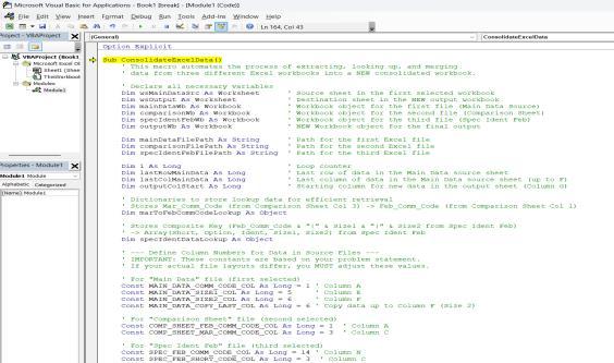
Fig-8:CorrectedVBAcodeinExcel Part1
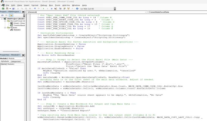
Fig-9:CorrectedVBAcodeinExcel Part2
• Modulescreatedforeachtask
• Functionsforcomparisonandextraction
• Excelautomationfordataprocessing
6.2C#Implementation
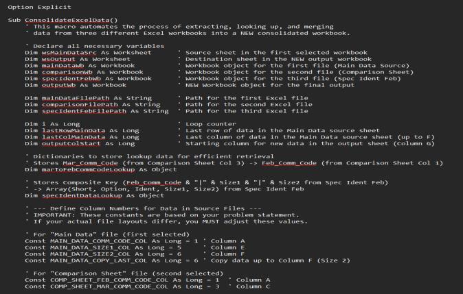
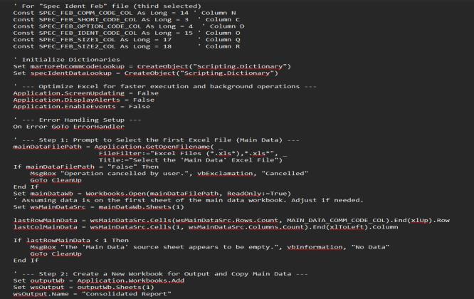
Fig-10:InitialtrialVBAcodeforMethod1comparison logic
• WindowsFormsusedforGUI
• Event-drivenprogramming
International Research Journal of Engineering and Technology (IRJET) e-ISSN: 2395-0056
Volume: 13 Issue: 04 | Apr 2026 www.irjet.net p-ISSN: 2395-0072
• Reduces manual effort by automating repetitive taskssuchasdatacomparisonandextraction
• Saves significant time compared to traditional manualmethods
• Improvesaccuracybyeliminatinghumanerrorsin largedatasetprocessing
• Provides fast and efficient comparison of specificationidentificationsheets
• Capable of handling large volumes of engineering data(highscalability)
• Organizesdataintoclearcategoriessuchasadded, modified,deleted,andskippedcomponents
• Enhancesreadabilityoforthographicdiagramsby simplifyingcomplexinstrumenttags
• Generatesstructuredoutputsforeasyanalysisand decision-making
• Improves coordination between design, procurement,andengineeringteams
• Reduces chances of data inconsistency and mismatchissues
• Increasesoverallproductivityofengineers
• User-friendly interface developed using C# enableseasyoperation
• Requiresminimaltechnicalexpertisetooperate
• Reduces project delays by speeding up data processingtasks
• Supports digital transformation in engineering workflows
• Flexibleandcanbeadaptedtosimilarengineering applications
8.LIMITATIONS
• Thesystemishighlydependentontheformatand structureofinputExcelfiles
• Any change in column names or file layout may causeerrorsinprocessing
• Limited compatibility with non-standard or corrupteddataformats
• Requires initial setup and configuration before execution
• ThetooloperatesmainlyonExcel-baseddataand lacks direct integration with design software like Smart3D
• Not fully automated in real-time; works on batch processingofdata
• RequiresbasicknowledgeofVBAorsystemusage fortroubleshooting
• Performancemayslightlydecreasewithextremely largedatasets(veryhighrows)
• Error handling is limited for unexpected input conditions
• GUI functionality is basic and may not support advancedvisualizationfeatures
• The tool is platform-dependent (primarily Windows-basedenvironment)
• Securityfeaturessuchasdataencryptionanduser authenticationarenotincluded
• Limited flexibility for customization without modifyingthesourcecode
• Does not include built-in backup or recovery mechanisms
• Integrationwithenterprisesystems(ERP/PLM)is notavailable
• Integration with advanced engineering software such as Smart 3D for real-time data synchronization
• Development of cloud-based platforms to enable remoteaccessandteamcollaboration
• Implementation of artificial intelligence (AI) for automatic error detection and smart decisionmaking
• Useofmachinelearningalgorithmstopredictdata inconsistenciesandsuggestcorrections
• Enhancement of real-time data processing capabilitiesforinstantupdatesandmonitoring
• Expansionofthetooltosupportotherengineering domains such as mechanical, electrical, and structuralengineering
• Development of a web-based interface for improvedaccessibilityacrossdifferentdevices
• Additionofadvanceddatavisualizationtoolssuch asdashboards,graphs,andreports
• Automationofadditionalengineeringtaskssuchas reportgenerationandvalidation
• Integration with enterprise systems like ERP and PLMforbetterdatamanagement
• Improvement in user interface design for better userexperienceandusability
• Implementationofstrongsecurityfeaturessuchas dataencryptionanduserauthentication
• Optimization of system performance to handle verylargedatasetsefficiently
• Developmentofmobileapplicationsupportforonsiteengineeringaccess
• Inclusion of automated backup and recovery systemsfordatasafety
• SupportformultiplefileformatsbeyondExcelfor greaterflexibility
International Research Journal of Engineering and Technology (IRJET) e-ISSN: 2395-0056
Volume: 13 Issue: 04 | Apr 2026 www.irjet.net p-ISSN: 2395-0072
This study addressed critical challenges in piping engineering workflows, particularly those related to data inconsistency, manual processing, and complex tagging systems commonly encountered in large-scale industrial projects.BydevelopingautomationtoolsusingVBAandC#, the project successfully streamlined the comparison of specificationidentificationsheets,identifieddiscrepancies in commodity codes, and enabled efficient extraction of skipped, modified, added, and deleted components from catalogue data. In addition, the implementation of a tag streamlining tool significantly improved the readability and usability of orthographic diagrams by converting complex instrument tags into simplified sequential identifierswhilemaintainingtraceabilitythroughmapping files. The results demonstrated a substantial reduction in manualeffort,processingtime,andhumanerrors,thereby enhancing overall workflow efficiency and accuracy. The integration of a user-friendly graphical interface further improvedaccessibilityandusability,allowingengineersto execute complex operations with minimal technical expertise.The studyhighlightsthegrowingimportance of automationinmodernengineeringpractices,emphasizing itsroleinimprovingproductivity,ensuringdatareliability, andsupportingeffectivecollaborationbetweendesignand procurement teams. Although certain limitations such as dependence on structured input formats and limited integration with external systems were identified, the proposedsolutionprovidesastrongfoundationforfuture advancements. Overall, the project confirms that automation is a key enabler in digital engineering transformationandoffersapractical,scalableapproachto improving piping engineering workflows in industrial applications.
Theauthorswouldliketoexpresstheirsinceregratitudeto the Department of Mechanical Engineering, VIT Pune, for providing the necessary facilities and academic environmenttocarryoutthiswork.Weextendourthanks to our project supervisor, Dr. G. Suresh Kannan, for his valuable guidance, constructive feedback, and continuous support throughout the project.We alsothank the faculty members and laboratory staff for their assistance during the design, modelling, and analysis stages, and we acknowledge our classmates and friends for their cooperationandsupport.
1. ASME B31.3, Process Piping, American Society of MechanicalEngineers,LatestEdition.
2. ASME B31.1, Power Piping, American Society of MechanicalEngineers,LatestEdition.
3. Nayyar, M. L., Piping Handbook, 7th Edition, McGraw-HillEducation,2000.
4. Smith,R., Chemical Process Design and Integration, WileyPublications,2005.
5. Bentley Systems, AutoCAD Plant 3D User Guide, AutodeskDocumentation.
6. Intergraph Corporation, Smart 3D (S3D) Software Documentation,HexagonPPM.
7. MicrosoftCorporation, VisualBasicforApplications (VBA) Documentation,MicrosoftDocs.
8. Microsoft Corporation, .NET Framework and C# Programming Guide,MicrosoftDocs.
9. Pressman, R. S., Software Engineering: A Practitioner’s Approach, 7th Edition, McGraw-Hill, 2010.
10. Sommerville, I., Software Engineering, 10th Edition,PearsonEducation,2016.
11. ISO15649, PetroleumandNaturalGasIndustries Piping, International Organization for Standardization.
12. Kellogg, D. W., Design of Piping Systems, Wiley Publications.
13. Rajput,R.K., MechanicalEngineeringDesign,Laxmi Publications.