
International Research Journal of Engineering and Technology (IRJET) e-ISSN: 2395-0056
Volume: 13 Issue: 03 | Mar 2026 www.irjet.net p-ISSN: 2395-0072
International Research Journal of Engineering and Technology (IRJET) e-ISSN: 2395-0056
Volume: 13 Issue: 03 | Mar 2026 www.irjet.net p-ISSN: 2395-0072
J.Jaya
Keerthana¹, S.Kiran Mohana Rao², V.Sri Vidya³, P.Aravin⁴, M.Dora Swamy Bhagya Raju⁵
¹ Assistant Professor,Dept. of Electronics and Communication Engineering Department, Seshadri Rao
Gudlavalleru Engineering College, Andhra Pradesh, India
²³´µStudent, Department of Electronics and Communication Engineering, Seshadri Rao Gudlavalleru Engineering college, Andhra Pradesh, India ***
Abstract- Industry 5.0 emphasizes the development of highly connected, intelligent, and sustainable communication ecosystems, where advanced 5G and emerging 6G technologies play a crucial role. Antennas serve as fundamental components in enabling these highspeed wireless networks, necessitating compact, wideband, and high-efficiency designs. In this work, a compact Rectangular microstrip antenna with hexagonal slots is designed and modelled for ultra-wideband (UWB) applications with a specific focus on 5G mobile communicationsystems.Thehexagonalgeometryisselected over conventional rectangular and circular patches due to its inherent advantages, including improved harmonic suppression, scalable bandwidth, and symmetric radiation characteristics, which contribute to reduced crosspolarization and enhanced multi-band performance. The proposed antenna is designed on a low-cost FR-4 substrate with a compact footprint of 30 mm × 30 mm and is optimizedtoachievewideimpedancebandwidthandstable radiation performance. To further enhance system reliabilityand channel capacity, the design is extended into aMultiple-InputMultiple-Output(MIMO)configuration.Key MIMO performancemetrics such as S-parameters, Envelope Correlation Coefficient (ECC), and diversity gain, Mean Effective Gain (MEG) are analysed and modelled using CST Microwave Studio and Google colab. A comparative evaluation with recent antenna designs demonstrates that theproposedMIMOantenna offerssuperiorperformance in terms of bandwidth, gain, compactness, and radiation efficiency. Owing to its compact structure, wideband characteristics, and improved MIMO performance, the proposed antenna is a promising candidate for nextgeneration 5G and future 6G wireless communication and Industry5.0applications.
Keywords antenna, Multiple-Input Multiple-Output (MIMO), Ultra-Wideband, Hexagonal Patch, FR-4 Substrate, Envelope Correlation Coefficient, Diversity Gain, 5G Communication.
The rapid advancement of wireless communication technologies has significantly increased the demand for high data rates, improved spectral efficiency, and enhanced link reliability. With the deployment of fifthgeneration (5G) and the ongoing research toward sixthgeneration(6G)systems,modernwirelessnetworksmust
support massive connectivity, ultra-low latency, and high throughput. One of the key technologies enabling these requirements is Multiple-Input Multiple-Output (MIMO) antennasystems.
MIMO technology employs multiple transmitting and receiving antennas to exploit spatial diversity and multipath propagation, thereby increasing channel capacity without requiring additional bandwidth or transmit power. Compared to conventional single-input single-output (SISO) systems, MIMO systems provide substantial improvements in data rate, signal reliability, and spectral efficiency. This makes MIMO an essential componentin4GLTE,5GNR,wirelesslocalareanetworks (WLAN), Internet of Things (IoT) devices, and future smartcommunicationinfrastructures.
MIMO technology employs multiple transmitting and receiving antennas to exploit multipath propagation effectively. Instead of treating multipath signals as interference,MIMOsystemsutilizethemtoimprovesignal strength and data throughput. The performance improvement is achieved through diversity gain and spatial multiplexing techniques. The theoretical diversity order of a MIMO system is given by the product of the number of transmit and receive antennas (Nt×Nr), which significantlyenhancessystemrobustnessagainstfading.
Microstrip patch antennas are widely used in MIMO configurations due to their low profile, lightweight structure, low fabrication cost, and compatibility with printed circuit board technology. However, designing compact MIMO antennas for Ultra-Wideband (UWB) and 5G applications presents challenges such as mutual coupling between antenna elements, high envelope correlation coefficient (ECC), and reduced isolation. Therefore, proper design techniques such as defected ground structures (DGS), orthogonal element placement, and neutralization lines are adopted to improve isolation andoverallMIMOperformance.
In this work, a compact MIMO antenna is designed and analysed to achieve wide impedance bandwidth, high isolation, low ECC, and stable radiation characteristics. The proposed design aims to provide enhanced diversity performance and improved spectral efficiency, making it suitable for next-generation 5G and future 6G wireless communicationapplications.
International Research Journal of Engineering and Technology (IRJET) e-ISSN: 2395-0056
Volume: 13 Issue: 03 | Mar 2026 www.irjet.net p-ISSN: 2395-0072
Ultra-wideband technology, which also enables users to wirelessly link a large number of devices and a large number of users in the areas of dispatch and reception, eliminates the need for cables for users of wireless systems.
The design of the proposed single Rectangular microstrip patch antenna with hexagonal slots is carried out to achieve compact size, wide impedance bandwidth, and stableradiationperformancesuitableformodernwireless communication applications. The hexagonal geometry is selected instead of conventional rectangular or circular shapesduetoitssymmetricalstructure,improvedcurrent distribution, and better harmonic suppression characteristics. The symmetrical configuration of the hexagon helps in achieving balanced radiation patterns andreducedcross-polarizationlevels.
The antenna is fabricated on an FR-4 dielectric substrate with an appropriate of 1.6mm thickness and dielectric constant 4.4 to maintain a balance between bandwidth, efficiency, and fabrication cost. A copper layer is used for both the radiating patch and the ground plane. The side length of the hexagonal patch is carefully optimized to resonate at the desired operating frequency of 3.75GHz. Theresonantfrequencyprimarilydependsontheeffective radius(orequivalentdimension)ofthehexagon,substrate permittivity,andthickness.
To enhance impedance matching and bandwidth performance, a microstripfeedlineis employed.The feed position is optimized to achieve minimum return loss (S11) at the operating frequency. Proper impedance matching ensures efficient power transfer between the transmission line and the radiating patch. The antenna design parameters are modelled and simulated using CST MicrowaveStudiotoanalysereturnloss,VoltageStanding Wave Ratio (VSWR), gain, and radiation pattern characteristics.
The optimized single antenna serves as the fundamental radiating element for further extension into a MIMO configuration. Its compact structure, stable radiation characteristics, and wideband response make it suitable for integration into advanced 5G and Ultra-Wideband (UWB)communicationsystems.
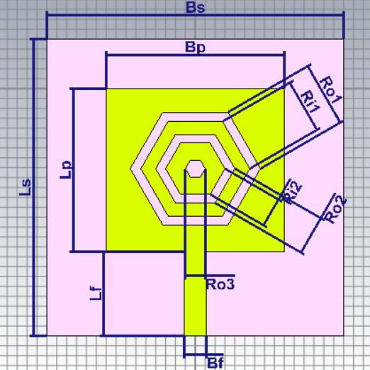
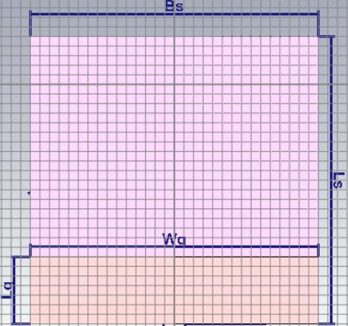
Figure1: SingleRectangularpatchwithhexagonalslotted antenna.
The proposed antenna is designed on a square dielectric substrate with overall dimensions Ls × Bs = 30 mm × 30 mm, where Ls represents the length of the substrate and Bs represents the width of the substrate. The radiating patch is placed at the center of the substrate with dimensions Lp × Bp = 16.5 mm × 18 mm. The antenna is excitedusingamicrostripfeedlinehavingalength(Lf)of 8.5 mm and width (Bf) of 2.30 mm, ensuring proper impedance matching. To enhance the antenna performance, concentric hexagonal slots are etched in the patch,wheretheouterhexagonalradius(Ro1)is5.50mm and the inner hexagonal radius (Ri1) is 4.00 mm. The spacingbetweentheslotsismaintainedat2.00mm,which increases the effective current path length and improves theimpedance bandwidth and radiation characteristics of theantenna.
Insidethepatch,concentrichexagonalslotsareintroduced to enhance the current distribution and improve the antenna performance. The outer and inner hexagonal slot radiiare5.50mmand 4.00 mm,respectively.Thespacing between the slots is maintained at 2.00 mm, which helps in increasing the effective current path length. This
International Research Journal of Engineering and Technology (IRJET) e-ISSN: 2395-0056
Volume: 13 Issue: 03 | Mar 2026 www.irjet.net p-ISSN: 2395-0072
modification improves the impedance bandwidth and radiationcharacteristicsoftheantenna.
The compact geometry, along with the slotted hexagonal structure and microstrip feed, enables the antenna to achieve improved bandwidth, good impedance matching, and stable radiation performance, making it suitable for widebandwirelesscommunicationapplications.
Table-1: PROPOSEDANTENNADIMENSIONVALUES
Due to fringing fields at the patch edges, the physical length of the antenna becomes slightly smaller than the effective length. The length extension caused by fringingfieldscanbecalculatedas

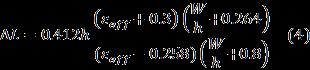
Thus,theactuallengthofthepatchantennais

The design calculations of the proposed antenna are performedusingthefundamentalparametersofthestrate andoperatingfrequency.
2.1 Design equations of a Microstrip patch antenna
The resonant frequency of a microstrip patch antenna primarily depends on the physical dimensions of the radiating element and the dielectric properties of the substrate
Thewidthofthemicrostrippatchcanbedeterminedusing
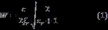
Theeffectiverelativedielectricconstantplaysasignificant role in determining the resonant length. It can be calculatedas:

where is the dielectric constant of the substrate, is the substratethickness,and isthewidthofthepatch.
The resonant frequency (fr) of the antenna is selected as 3.75 GHz. The antenna is fabricated on an FR4 substrate with a dielectric constant of 4.4 and a substrate thickness (h)of1.6mm.Thespeedoflightinfreespace(c)istaken as (3*10^8) m/s, which is used in determining the patch dimensions and resonant characteristics of the antenna. These parameters are utilized in the standard microstrip antenna design equations to calculate the effective dielectricconstant,patchwidth,andeffectivelengthofthe antenna.
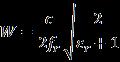





Theeffectivelength ofthepatchisgivenby:


where is the speed of light and is the resonant frequency. The actual physical length of the patch is then obtained by subtracting the fringing field extension fromtheeffectivelength.




International Research Journal of Engineering and Technology (IRJET) e-ISSN: 2395-0056
Volume: 13 Issue: 03 | Mar 2026 www.irjet.net p-ISSN: 2395-0072
4. Fringing Length Extension


5. Actual Patch Length



These analytical equations provide the initial design dimensions of the antenna. The final dimensions are further optimized to achieve the required dual-band performance, improved return loss, and enhanced radiationefficiency.
Patch Antenna
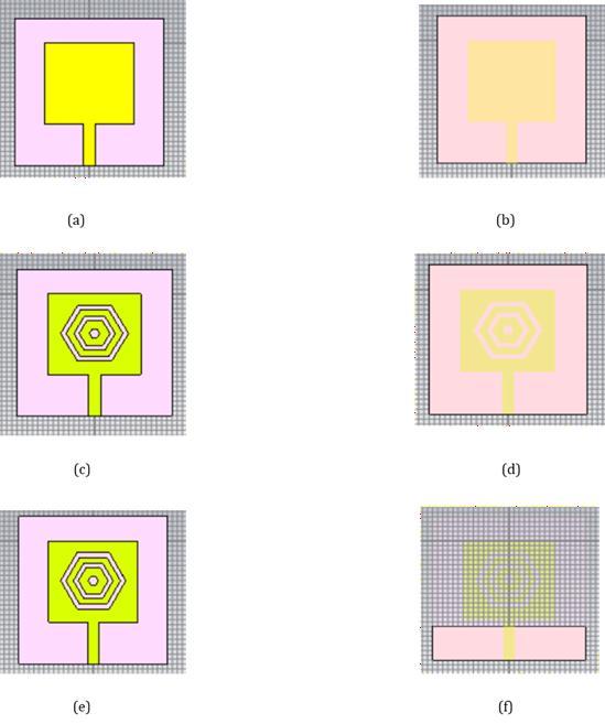
Figure2: EvolutionstagesofDesignofMicrostripPatch Antenna.
The figure illustrates the step-by-step design evolution of the proposed microstrip patch antenna. Initially, a basic rectangular microstrip patch with a microstrip feed line is designed on the substrate to obtain the fundamental resonant characteristics. In the second stage, hexagonal slot structures are introduced on the radiating patch, which modify the surfacecurrentdistributionandhelpinimprovingthe bandwidth and impedance matching. Further optimization is performed by adjusting the slot
geometry and patch structure to achieve better radiation performance. Finally, the complete optimized antenna structure along with the ground plane configuration is obtained, which enhances the overall antenna characteristics such as gain, bandwidth, and return loss, making the antenna suitable for the desired 3–5 GHz wireless communicationapplications.
Table -2: Characteristicsofthe developedantennawithPartialGroundatvarious steps
Type of antenna design st ructure
Rectangula rMicrostri ppatchant ennawithf ullGround
Rectangula rMicrostri ppatchant ennawith hexagonal slotsandfu llGround
Rectangula rMicrostri ppatchant ennawith hexagonal slotsandP artial Ground
2.3 Results of microstrip patch
The performance of the designe microstrip patch antenna is evaluated using S-parameters and Voltage Standing WaveRatio(VSWR).
2.3.1 S-parameter
Scatteringparameters,commonlyknownasS-parameters, are widely used to analyse the performance of antennas and high-frequency microwave circuits. They describe
International Research Journal of Engineering and Technology (IRJET) e-ISSN: 2395-0056
Volume: 13 Issue: 03 | Mar 2026 www.irjet.net p-ISSN: 2395-0072
how radio frequency (RF) signals behave when they encounter a network, particularly how much power is reflected, transmitted, or coupled between different ports oftheantennasystem.
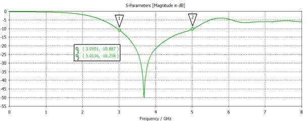
Figure3: S-parametersoftheproposedMicrostrippatch antenna.
The S-parameter (S11) plot shows the reflection coefficient of the proposed antenna over the frequency range. From the graph, a deep resonance occursaround3.7GHz, wherethereturnloss reaches approximately−48dB,indicatingexcellentimpedance matching and very low signal reflection. Additional pointsareobservedat3.0GHzand5.0GHz,wherethe returnlossvaluesareabout−10.87dBand−10.35dB, respectively, which are below the −10 dB threshold and therefore considered acceptable for antenna operation. This indicates that the antenna provides good impedance matching and operates efficiently withinthe3–5GHzfrequencyband.
2.3.2 VSWR
Voltage Standing Wave Ratio (VSWR) is an important parameter used to evaluate the impedance matching between the antenna and the transmission line. For efficient antenna operation, the VSWR value should ideally be close to 1 and typically less than 2 withintheoperatingfrequencyband.
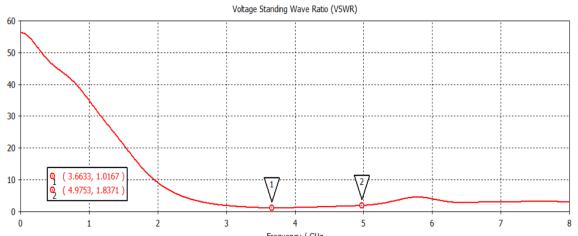
Figure 4: VSWRoftheproposedMicrostrippatch antenna.
Fromthegraph,theantennaexhibitsa minimumVSWRof approximately1.11ataround3.7GHz,indicatingexcellent impedance matching at the resonant frequency. Another pointisobservedat 4.98GHzwithaVSWRvalueofabout 1.84,whichisstillwithintheacceptablelimitof VSWR<2 for efficient antenna operation. The VSWR remains close to unity in the 3–5 GHz frequency range, confirming that the antenna provides good impedance matching and minimal power reflection in this band. This demonstrates that the antenna is suitable for mid-band wireless
communication applications, offering stable performance andefficientradiationcharacteristicswithintheoperating band.
This section provides a parametric analysis of a hexagon UWB antenna. The degree bandwidth and radiation designs of these setups have been assessed to make sure theyarecompatiblewiththeexpectedresults.
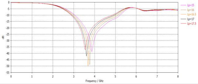
Patch-length (Lp) is another important design parameter for setting an appropriate resonant frequency of the antenna. An increase in Lp increases the electrical length of the antenna, which in turn reduces the resonant frequency all the way to Lp. Decreasing it will make Lp resonateathigherfrequencies.
Inoursimulations,areducedLpresultedindegradationin impedance matching, thereby resulting in a weak signal and bandwidth. After experimenting with various values, an Lp value of 16.5 mm achieved the best compromise to give a resonant frequency of 3.75 GHz with excellent returnlossS11=-50dB.
ParametricanalysisofdevelopedantennaPatch length(Lp)
Thelengthofground(Lg)isanimportant consideration that affects the bandwidth and radiation efficiency. A largerLgwillshifttheresonantfrequencylower,although it may narrow the bandwidth and thus affect the overall antenna performance. On the other hand, an excessively small Lg may cause impedance mismatches, resulting in high S11 values and losses in efficiency. The best overall tuning was achieved at Lg = 34.5mm in that 4.9 GHz bandwidth was maintained at decent antenna performancewithstableradiationpatterns.
International Research Journal of Engineering and Technology (IRJET) e-ISSN: 2395-0056
Volume: 13 Issue: 03 | Mar 2026 www.irjet.net p-ISSN: 2395-0072
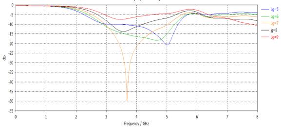
Figure 6: Parametricanalysisofdevelopedantenna Groundlength(Lg)
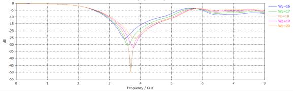
The patch width (Wp) takes an important role in shaping the input impedance and surface current distributions. Wider patches generally improve gain and radiation efficiency; however, if the patch becomes too wide, unwanted resonances may result which affect impedance matching. Tests showed that S11 values improved as Wp increaseduntilacertainlimitwasobtained,beyondwhich variations in gain occurred. Wp = 18 mm appears ideally balanced,givingareturnlossof-50dB.
Parametricanalysisofdevelopedantenna Patchwidth(Wp)
The substrate length (Ls) dictates the mode of wave propagation in the antenna and has an influence on bandwidth and impedance stability. A bigger Ls means that the substrate is a good supporter for surface wave propagation, but withanincrease in microwavedielectric losses.Lsmustnotbetoosmallbecauseinthisway,it will limit current flow and eventually affect impedance matching and bandwidth. Through trial and error, an optimum Ls of 32 mm showed to provide an efficient performance with broadband response and stable impedancecharacteristicssubjecttominimumlosses.
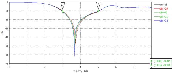
Figure 8: Parametricanalysisofdevelopedantenna LengthofSubstrate.
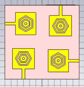
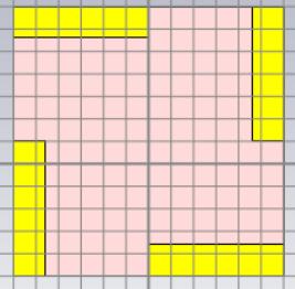
The suggested antenna is made up of four individual antenna components arranged in orthogonal orientations to create a MIMO prototype. The four identical antenna components are assembled into a Printed Circuit Board (PCB), which has three layers of patch, ground, and dielectricsubstrate.Thesamecomponentsareutilizedfor the single element that is suggested and has the dimensions60×60*1.6mm3inFig.6.
A)FRONTVIEW
B)BACKVIEW
Figure 9: TheMIMOantenna
To evaluate the performance of MIMO antennas, several important parameters are analysed, including Envelope Correlation Coefficient (ECC), Diversity Gain (DG), Mean Effective Gain (MEG), Channel Capacity Loss (CCL), and TotalActiveReflectionCoefficient(TARC).
5.1 Envelope Correlation Coefficient (ECC)
Envelope Correlation Coefficient (ECC) is an important parameter in MIMO antenna systems that measures the correlation between radiation patterns of different antenna elements. It indicates how independently the antennasoperatefromeachother.InagoodMIMOsystem, each antenna should transmit and receive signals independently to achieve high diversity and improved channelcapacity.ECCvaluesrangefrom0to1.
International Research Journal of Engineering and Technology (IRJET) e-ISSN: 2395-0056
Volume: 13 Issue: 03 | Mar 2026 www.irjet.net p-ISSN: 2395-0072
ForpracticalMIMOantennas,ECCshouldbelessthan0.5, and for high-performance systems, it is preferably less than 0.05. Lower ECC results in better diversity gain, improved signal reliability, andhigher data throughput in wirelesscommunicationsystems.

The above equation depicts the envelope correlation betweentheantennas��and��inthe(��,��)MIMOsystem.In case of ��= 1, ��=2 and��=4, the envelope correlation of proposedMIMOantennacanbedefinedasfollows
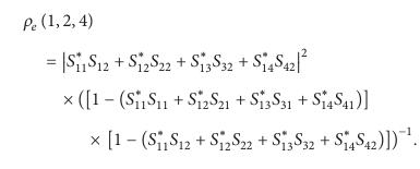
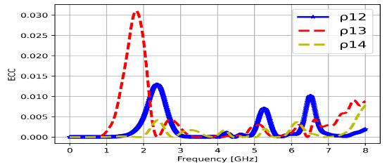
The Envelope Correlation Coefficient (ECC) of the proposed MIMO antenna remains very low across the operating frequency range, with peak values below 0.03. Such low ECC values (less than 0.05) indicate excellent isolation and minimal correlation between antenna elements. This confirms good diversity performance and effectiveMIMOoperationovertheUWBband.
5.2 Diversity Gain (DG)
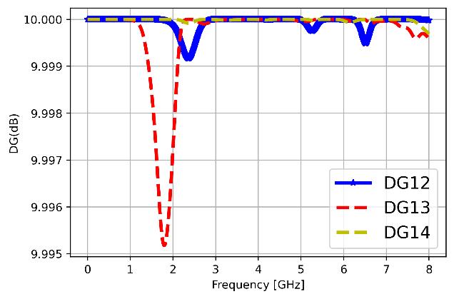
Diversity Gain (DG) in a MIMO antenna system refers to the improvement in signal reliability achieved by using multipleantennaelementstocombatmultipathfading.DG istypicallycloseto10dB,whichindicatesstrongdiversity performance and low correlation between antenna elements. A higher diversity gain means better signal stability, improved link quality, and enhanced overall communicationreliability.
5.3
Mean Effective Gain (MEG) is a MIMO antenna parameter thatrepresentstheaverage receivedpowerofanantenna element in a multipath propagation environment. It evaluates how effectively each antenna receives signals when waves arrive from different directions with varying polarizations. Ideally, the ratio of MEG between any two antenna elements should be close to 1 (or within ±3 dB). Proper MEG balance helps achieve better diversity performance, improved signal quality,and higher channel capacityinMIMOcommunicationsystems.

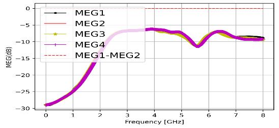
Figure 12: MeanEffectiveGain(MEG)
The MEG curves of all four antenna elements are nearly identical across the operating band, indicating uniform radiation performance in the MIMO configuration. The difference between MEG1 and MEG2 remains close to 0 dB,satisfying the acceptable diversity condition (|MEG1 –MEG2|<3dB).Thisconfirmsbalancedpowerdistribution andgoodMIMOefficiency.
5.4 Total Active Reflection Coefficient (TARC)
Total Active Reflection Coefficient (TARC) measures the overall reflection performance when multiple antenna portsareexcitedsimultaneously.
TARC is calculated using the reflected and incident voltage waves fromall antenna ports,andfor goodMIMO performance, its value should generally be below –10 dB within the operating frequency band. A lower TARC
International Research Journal of Engineering and Technology (IRJET) e-ISSN: 2395-0056
Volume: 13 Issue: 03 | Mar 2026 www.irjet.net p-ISSN: 2395-0072
indicates better impedance matching, reduced mutual coupling, and improved overall efficiency of the MIMO antennasystem.

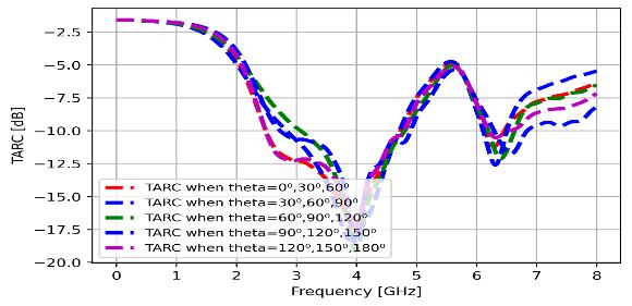
Figure 13: TotalActiveReflectionCoefficient
In the plot TARC remains below −10 dB over the main operating bands(3-5GHz) for different excitation phase angles, indicating good impedance matching in the MIMO configuration.Thecurvesshowconsistentbehavioracross various theta combinations, demonstrating stable multiport performance.Thisconfirmsefficient powerradiation and reliable MIMO operation across the UWB frequency range.
Channel Capacity Loss (CCL) is a key performance parameter in MIMO antenna systems that quantifies the reduction in theoretical maximum data transmission capacity due to correlation and mutual coupling between antenna elements. CCL is calculated using S-parameters and reflects how much the real antenna deviates from ideal behavior. For good MIMO performance, the Channel Capacity Loss should typically be less than 0.4 bits/Hz within the operating frequency band. A lower CCL indicates better isolation, lower correlation, and higher datathroughputcapability.

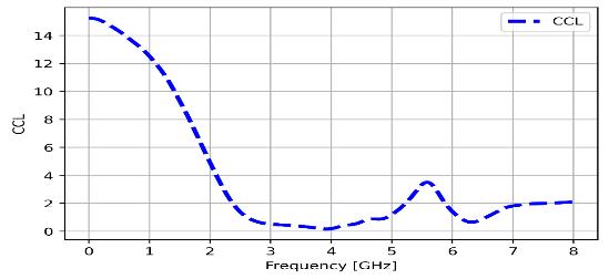
Inthe3–5GHzfrequencyrange,theChannelCapacityLoss (CCL) remains very low, approximately close to 0–0.5 bits/s/Hz. This indicates minimal loss in channel capacity andlowcorrelationbetweentheantennaelements.Hence, theMIMOantennaexhibitsefficientdiversityperformance andreliableoperationwithinthisband.
In this work, a compact rectangular microstrip patch antenna with hexagonal slots has been designed and analysed for ultra-wideband wireless communication applications. The antenna is simulated on an FR-4 substrate with compact dimensions of 30 mm × 30 mm and operates within the 3–5 GHz frequency band, making it suitable for 5G communication systems. The proposed antenna achieves a resonant frequency of 3.75 GHz with excellent impedance matching, where the return loss reaches approximately −50 dB and the VSWR value is around1.1,indicatingefficientpowertransfer.
The design is further extended to a 4 × 4 MIMO configuration to enhance channel capacity and system reliability. Key MIMO performance parameters such as Envelope Correlation Coefficient (ECC), Mean Effective Gain (MEG), Total Active Reflection Coefficient (TARC), and Channel Capacity Loss (CCL) are analysed. The ECC value remains below 0.03, indicating low correlation and excellent diversity performance. Additionally, the CCL remains within acceptable limits, confirming minimal capacityloss.
Therefore, due to its compact size, wide bandwidth, good impedance matching, and strong MIMO performance, the proposedantennaisasuitablecandidatefor5G,future6G wireless systems, and Industry 5.0 communication applications.
[1] X.WeiHighisolationMIMOantennasystemfor5G N77/N78/N79bands,”Micromachines,vol.15,no. 6,721,2024.
[2] R.M. Asif, A.U. Rehman,S.Guizani, and H.Hamam,“Enhancing spectral efficiency in uplink/downlink channels of multi-cell massive MIMO for 5G networks,” International Journal of AdvancedandApplied Sciences,vol.11, no. 8,pp. 66−79,2024.
[3] L. Chang, G. Zhang, and H. Wang, “Triple-band microstrip patch antenna and its four-antenna module based on half-mode patch for 5G 4 × 4 MIMOoperation,”IEEETransactionsonAntennas and Propagation, vol. 70, no. 1, pp. 67−74, Jan. 2022.
International Research Journal of Engineering and Technology (IRJET) e-ISSN: 2395-0056
Volume: 13 Issue: 03 | Mar 2026 www.irjet.net p-ISSN: 2395-0072
[4] N. Anjum, Z. Yang, I. Khan, M. Kiran, F. Wu et al., “Efficient algorithms for cache-throughput analysisincellular-d2d5gnetworks,”Computers, Materials and Continua, vol. 67, no. 2, pp.1759–1780,2021.
[5] T. Upadhyaya, I. Park, R. Pandey, U.Patel, K. Pandya, A. Desai, J.Pabari, G. Byun, and Y. Kosta, “Aperture-fed quad-port dual-band dielectric resonator-MIMO antenna for Sub-6 GHz 5G and WLAN application,” International Journal of Antennas and Propagation, vol. 2022, pp. 1−13, Aug.2022.
[6] C.Z.Han,L.Xiao,Z.Chen,andT.Yuan,“Co-located self-neutralized handset antenna Pairs with complementary radiation patterns for 5G MIMO applications,” IEEE Access, vol. 8, pp. 73151−73163,2020.
[7] W. Hu et al., “Wideband back-cover antenna design using dual characteristic modes with high isolation for 5G MIMO smartphone,” IEEE Transactions on Antennas and Propagation, vol. 70,no.7,pp.5254−5265,July2022.
[8] A. J. A. A. Gburi et al., “Broadband circular polarised printed antennas for indoor wireless communication systems: A comprehensive review,” Micromachines, vol. 13, no. 7, 1048, Jun. 2022.
[9] X. Tian et al., “Power allocation scheme for maximizing spectral efficiency and energy efficiency tradeoff for uplink noma systems in B5G/6G,” Phys. Commun., vol. 43, 101227, Dec. 2020.
[10] T. Y. Elganimi and K. M. Rabie, “Time-indexed parallel spatial modulation for large-scale MIMO systems with antenna grouping,” in Proc. of IEEE 93rd Vehicular Technology Conference (VTC2021-Spring), Helsinki, Finland, 2021, pp. 1−5.
[11] R.Hussain,A.T.Alreshaid,S.K.Podilchak,andM. S. Sharawi, “Compact 4G MIMO antenna integrated with a 5G array for current and future mobile handsets,” IET Microw. Antennas Propag., vol.11,no.2,pp.271–279,2017.
[12] M. Ahmed et al., “A blockchain-based emergency message transmission protocol for cooperative VANET,” IEEE Transactions on Intelligent Transportation Systems, vol. 23, no. 10, pp. 19624−19633,Oct.2022.
[13] A. U. Makarfi, K. M. Rabie, O. Kaiwartya, O. S. Badarneh, X. Li, and R. Kharel, “Reconfigurable intelligent surface enabled IoT networks in generalized fading channels,” in Proc. of IEEE International Conference on Communications (ICC),Dublin,Ireland,2020,pp.1−6.
[14] Y. Kabalci, “5G mobile communication systems: Fundamentals, challenges, and key technologies,” inSmartGridsandTheirCommunicationSystems, Berlin, Germany: Springer, Sep. 2019, pp. 329–359.
[15] F. A. Ogaili and R. M. Shubair, “Millimeter-wave mobile communications for 5G: Challenges and opportunities,” in Proc. of IEEE International Symposium on Antennas and Propagation (APSURSI), Fajardo, PR, USA, 2016, pp. 1003−1004.
[16] I. Rasheed, M. Asif, A. Ihsan, W. U. Khan, M. Ahmed,andK.M.Rabie,“LSTM-Baseddistributed conditional generative adversarial network for data-driven communications,” IEEE 5G-Enabled maritime UAV Transactions on Intelligent Transportation Systems, Early Access, vol. 24, no. 2,pp.2431−2446,2022.
[17] P. R. Girjashankar, T. Upadhyaya, and A. Desai, “Multiband hybrid MIMO DRA for Sub-6 GHz 5Gand WiFi-6 applications,” International Journal of RF and Microwave Computer‐Aided Engineering,vol.32,no.12,pp.1–18,Dec.2022.
[18] U.Pateland T.Upadhyaya,“Four-portdual-band multiple-input multiple-output dielectric resonator antenna for sub-6 GHz 5G communicationapplications,”Micromachines,vol. 13,no.11,pp.1−17,Nov.2022.
[19] A. F. M. S. Shah, “A survey from 1G to 5G includingtheadventof6G:Architectures,multiple accesstechniques,andemergingtechnologies,”in Proc. of IEEE 12th Annual Computing and Communication Workshop and Conference (CCWC), Las Vegas, NV, USA, 2022, pp. 1117−1123.
[20] Y.Zhang,J.Du,Y.Chen,X.Li,K.M.Rabie, andR. Kharel, “Near optimal design for hybrid beamforming in mmWave massive multi user MIMO systems,” IEEE Access, vol. 8, pp. 129153−129168,2020.
International Research Journal of Engineering and Technology (IRJET) e-ISSN: 2395-0056
Volume: 13 Issue: 03 | Mar 2026 www.irjet.net p-ISSN: 2395-0072
[21] M. B. Yassein, S. Aljawarneh, and A. A. Sadi, “Challenges and features of IoT communications in 5G networks,” in Proc. of International Conference on Electrical and Computing Technologies and Applications (ICECTA), Ras Al Khaimah,UnitedArabEmirates,2017,pp.1−5.
[22] A. Ahad, M. Tahir, M. Aman Sheikh, K. I. Ahmed, A. Mughees, and A. Numani, “Technologies trend towards 5G network for smart health-care using IoT: A review,” Sensors, vol. 20, no. 14, 4047, Jul. 2020.
[23] S.Talwar, D.Choudhury,K. Dimou,E.Aryafar,B. Bangerter and K. Stewart, “Enabling technologies andarchitecturesfor5Gwireless,”inProc.ofIEEE MTT-S International Microwave Symposium (IMS2014),Tampa,FL,USA,2014,pp.1−4.
[24] B.M.ZerihunandY.Wondie,“MassiveMIMOfor 5G cellular networks: Potential benefits and challenges,” Lecture Notes of the Institute for Computer Sciences, Social Informatics and Telecommunications Engineering, pp. 219–227, 2018.
[25] M. Han, J. Du, Y. Zhang, X. Li, K. M. Rabie and G. Nauryzbayev, “Efficient hybrid beamforming design in mmWave massive MU MIMO DF relay systems with the mixed-structure,” IEEE Access, vol.9,pp.66141−66153,2021.
[26] G. Irene and A. Rajesh, “A dual-polarized UWB–MIMO antenna with IEEE 802.11ac band-notched characteristics using split-ring resonator,” J. Comput. Electron., vol. 17, no. 3, pp. 1090–1098, Sep.2018.
[27] A.Khoshniat,“Alinearlyandcircularlypolarized active integrated antenna,” Utah State University, 2011.
[28] S. Saxena, B. K. Kanaujia, S. Dwari, S. Kumar, H. C. Choi, and K. W. Kim, “Planar four-port dual circularly-polarizedMIMOantenna for Sub-6 GHz band,” IEEE Access, vol. 8, pp. 90779−90791, 2020.
[29] T. Duong, N. T. B. Phuong, P. D. Son, and V. V. Yem, “Improving characteristics of 28/38 GHz MIMO antenna for 5G applications by using double-side EBG structure,” Journal of Communications,vol.14,pp.1−8,2019.
[30] S. P. Dubazane, P. Kumar, and T. J. O. Afullo, “Metasurface superstrate-based MIMO patch antennas with reduced mutual coupling for 5G communications,” The Applied Computational
Electromagnetics Society Journal (ACES), pp. 408−419,2022.
[31] T. Alam, M. Faruque, and M. Islam, “A doublenegative metamaterial-inspired mobile wireless antenna for electromagnetic absorption reduction,”Materials,vol.8,no.8,pp.4817–4828, Jul.2015.
[32] M. Islam, F. Ashraf, T. Alam, N. Misran, and K. Mat,“Acompactultrawidebandantennabasedon hexagonal split-ring resonator for pH sensor application,” Sensors, vol. 18, no. 9, 2959, Sep. 2018.
[33] J.M.Benlliure,M.C.Fabrés,E.A.Daviu,andM.F. Bataller, “Sector unit-cell methodology for the design of sub-6 GHz 5G MIMO antennas,” IEEE Access,vol.10,pp.100824−100836,2022.
[34] Z. Ji et al., “Low mutual coupling design for 5G MIMO antennas using multi-feed technology and its application on metal-rimmed mobile phones,” IEEEAccess,vol.9,pp.151023−151036,2021.
[35] S.Li,B.Fu,andW.Cao,“AminiaturedHexagonshaped UWB Antenna,” in Proc. of IEEE 3rd International Conference on Electronic Information and Communication Technology (ICEICT),Shenzhen,China,2020,pp.184−187.
[36] A. Azari, “A new super wideband fractal microstrip antenna,” IEEE Transactions on Antennas and Propagation, vol. 59, no. 5, pp. 1724–1727,May2011.
[37] S. F. Jilani and A. Alomainy, “Millimetre-wave Tshaped MIMO antenna with defected ground structures for 5G cellular networks,” IET Microwaves, Antennas & Propagation, vol. 12, no. 5,pp.672–677,Apr.2018.
[38] Y. Zhang, J. Du, Y. Chen, X. Li, K. M. Rabie, and R. Kharel, “Dual-iterative hybrid beamforming design for millimeter-wave massive multi-user MIMO systems with sub-connected structure,” IEEE Transactions on Vehicular Technology, vol. 69,no.11,pp.13482–13496,Nov.2020.