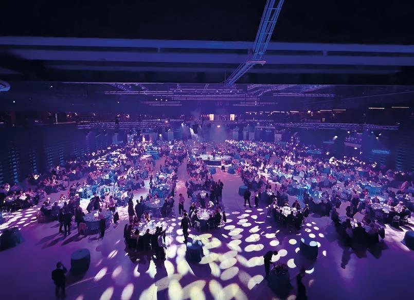
Introducing the platform for holistic port solutions
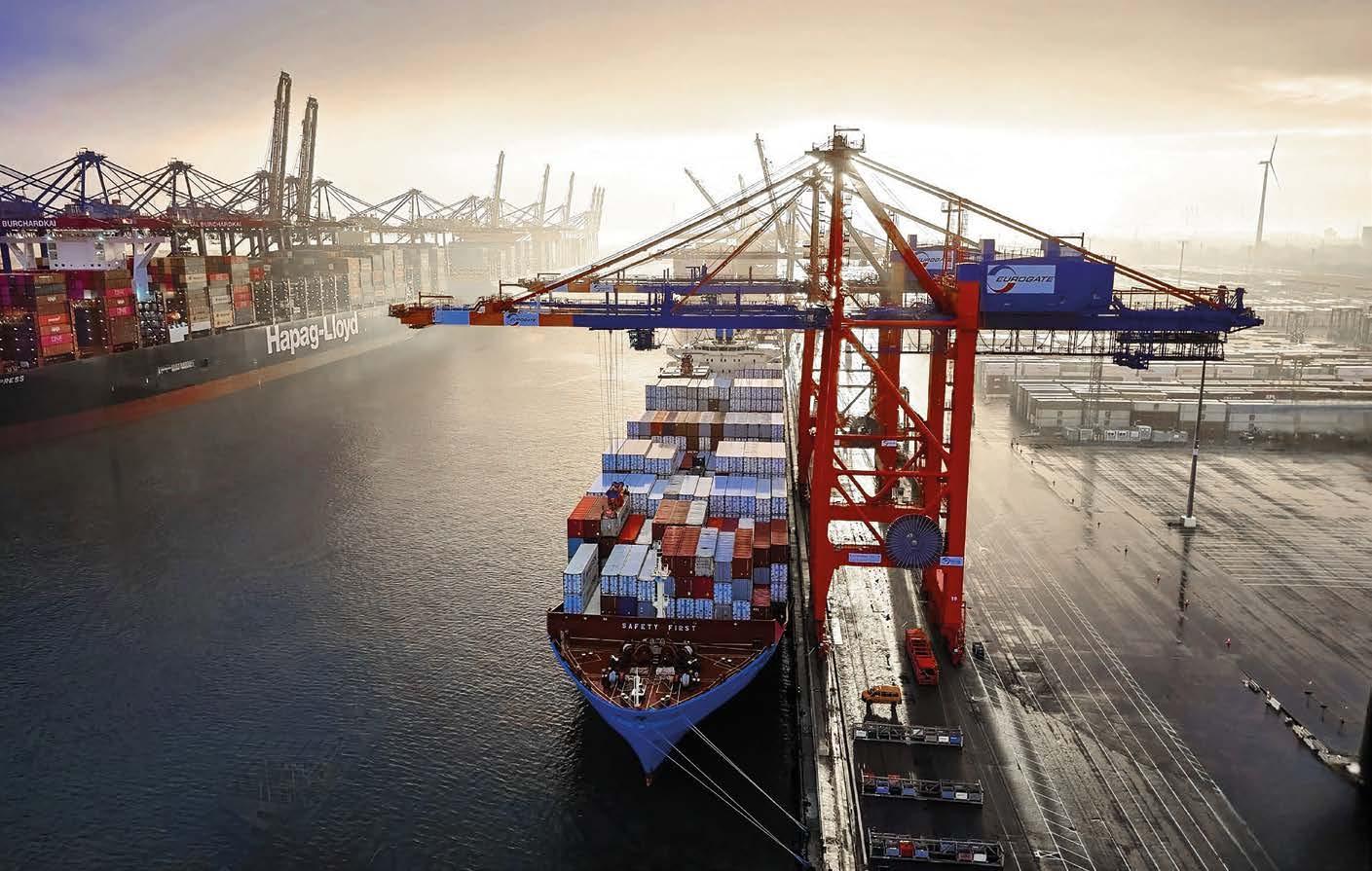
ALL ABOUT PORTS is the first event to take a holistic view of the transition of port infrastructure and operations – and to provide solutions designed to support cutting-edge multidisciplinary approaches.
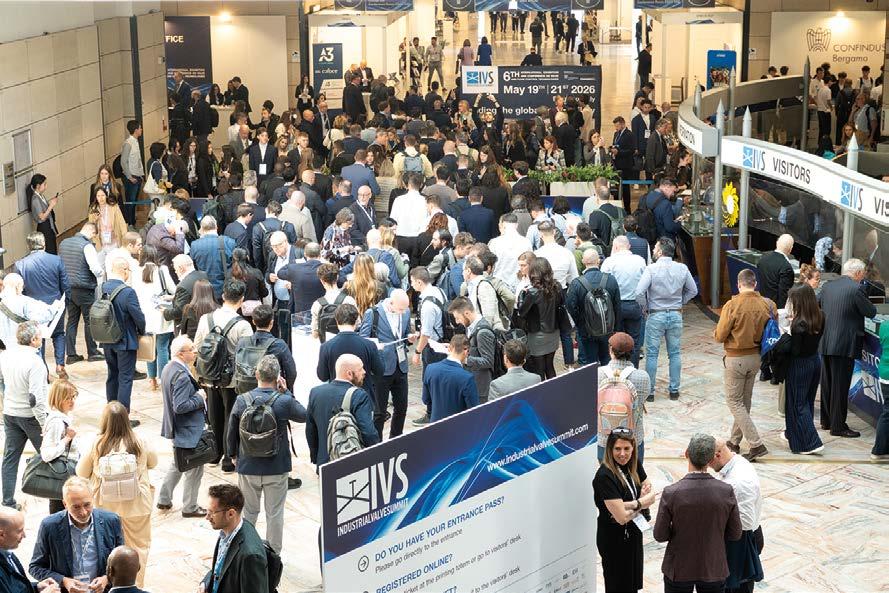
Connect with industry leaders and innovators at the two-day conference and accompanying exhibition covering all aspects of port security, sustainability, logistics, autonomous port terminals, digitalisation, and smart bunkering.
Join us in Hamburg, the place where tomorrow’s port technology is tested today, alongside SMM, the world’s leading maritime industry event.
Register here
Alessia Venturi
Editor-in-chief
Artificial intelligence algorithms are learning to recognise correlations that even the most experienced specialists may overlook. By crossreferencing thousands of inspections, climate data, operational parameters, and maintenance schedules, they can identify recurring patterns, estimate the likelihood of deterioration, and recommend when and where to take action.
EDITOR FROM THE
Corrosion always leaves a trace, and over more than a century, humankind has learned to decipher it: a rust stain, a flaking coating, a loss of thickness, a crack. This ability to interpret the past gave rise to modern corrosion protection engineering. Today, however, we are entering a new phase: understanding what has happened is no longer enough; we must be able to predict what will happen.
The future of corrosion is increasingly shaped by the collection, interpretation, and management of data, with a shift from reactive to predictive approaches.
But what data? Field data: valuable information that gives us a real-world picture of corrosion, outside the controlled conditions of the laboratory.
Every inspection carried out on a pipeline, every survey conducted on an offshore platform, and every thickness measurement recorded during a maintenance shutdown are much more than a simple snapshot of a plant’s current status. These are fragments of knowledge that, if collected and organised correctly, describe the actual behaviour of materials under their real operating conditions.
For years, this data has been confined to paper reports, spreadsheets, and archives that were difficult to consult. Today, however, it is becoming the heart of a new generation of digital tools capable not only of storing information but also of transforming it into predictions.
Artificial intelligence algorithms are, in fact, learning to recognise correlations that even the most experienced specialists may overlook. By cross-referencing thousands of inspections, climate data, operational parameters, and maintenance schedules, they can identify recurring patterns, estimate the likelihood of deterioration, and recommend when and where to take action.
This evolution finds its most tangible expression in digital twins. A digital twin is not simply a virtual replica of a structure: it is a digital organism that grows alongside the physical asset, is continuously updated with fieldcollected data, and enables the simulation of the system’s future behaviour. It is like a permanent laboratory where different scenarios can be tested without interrupting production or waiting for damage to occur.
The positive implications of this data-driven future are clear. Inspections can be planned based on actual risk rather than on pre-set deadlines. Financial resources are channelled where they are genuinely needed. Errors of judgement are reduced because decisions are based on a much greater volume of information than in the past. And maintenance ceases to be a reaction to emergencies and becomes a strategic planning tool.
Of course, the quality of the data collected in the field, its standardisation, and the ability to share it across the supply chain constitute the human element of this approach: designers, inspectors, installers, plant operators, and technology manufacturers all play a vital role in this datadriven culture.
For many years, we have regarded corrosion as an inevitable phenomenon that can only be contained. Now, we are beginning to treat it as a process that needs to be understood, controlled, and anticipated. We will be glad to discuss this with exhibitors and visitors at numerous trade fairs across various industrial sectors this autumn: SMM and Wind Energy in Hamburg, Innotrans in Berlin, Eurocorr in Dublin, ENES2026 in Warsaw, and AIM in Brescia.
The future of corrosion management lies not only in materials or coatings, but also in the ability to transform millions of data points collected in the field into better decisions. This is perhaps the most advanced form of protection technology can offer us.
NEW WHAT’S
EcoCortec and Orqa partner to shield global drone shipments from corrosion and ESD with sustainable packaging
EcoCortec®, a premier European manufacturer of environmentally friendly packaging specializing in Vapour phase Corrosion Inhibitor (VpCI®) technology, has developed a customspecification, grey version of its recyclable EcoSonic® VpCI®-125 ESD packaging specifically for Orqa.
In a major development for the Croatian technology sector, two of the nation’s leading exporters, EcoCortec® and Orqa, have announced a strategic partnership to secure high-end electronics for global defence and industrial markets.
Based in Osijek, Orqa is Europe’s leading drone technology company, specialising in First Person View (FPV) and Remote Reality (RR) technology. The company designs and manufactures advanced unmanned aerial systems. Its fully vertically integrated operations ensure complete supply chain independence and unmatched performance optimisation. The company’s exceptional trajectory was highlighted in 2026 when it ranked #135 overall and #2 in Aerospace & Defence on The Financial Times’ FT1000 list of Europe’s fastest-growing companies. Orqa now produces components and integrated systems for clients across more than 50 markets worldwide, including 24 NATO member states.
A defining feature of this collaboration is the geographical proximity of the two entities. EcoCortec’s manufacturing plant is situated in Beli Manastir, whilst Orqa’s headquarters are located just 20 minutes away in Osijek, creating a highly efficient, ‘just-intime’ supply chain. By sourcing technical materials from a local supplier, Orqa successfully avoids the logistical challenges and high costs associated with international imports. This localised approach grants significant environmental and operational benefits:
The short transit distance dramatically cuts down on transport emissions.
It enables rapid response times and immediate delivery capabilities.
Because the EcoSonic® VpCI®-125 ESD bags are fully recyclable, the supply chain remains entirely sustainable and waste-free. In an industry where speed is paramount, having a partner virtually next door allows for seamless transitions from production to global shipping without international delays.
For Orqa, whose unmanned aerial vehicles operate in the most demanding environments on Earth, specialised packaging is critical. During global transit, electronic hardware faces two severe threats: salt-air corrosion and electrostatic discharge (ESD).
This level of robust protection is absolutely vital for military and defence projects, where equipment is frequently stored for extended periods or transported through extreme humidity. The use of EcoCortec’s non-toxic VpCI® bags guarantees that sensitive devices, such as Orqa’s MRM2-10 drone, do not suffer operational failures caused by rust or static electricity. This identical reliability is equally essential for industrial applications, including the inspection of offshore oil rigs or power grids, where hardware must remain in flawless condition despite harsh, saline environments.
By merging specialised chemical engineering with worldclass aerospace electronics, EcoCortec® and Orqa are firmly positioning Croatia as a serious provider of sophisticated, end-toend technological solutions capable of competing at the highest international levels. This alliance enables Orqa to maintain a thoroughly European, sustainable supply chain that satisfies the most rigid global standards for reliability and performance.
“Our collaboration with our fellow Croatian neighbours shows that companies don’t have to look outside our borders for world-class innovation. By keeping things local, we ensure the supply chain stays reliable and eco-friendly, meeting the same strict international standards as the world’s top tech firms,” has commented Boris Miksic, CEO of EcoCortec.
www.cortecvci.com
AkzoNobel powers up protection for China’s landmark green energy project
The project aligns closely with AkzoNobel’s own aggressive climate goals. The paints and coatings supplier has already slashed its own Scope 1 and 2 emissions by 47%, heavily driven by increasing its renewable electricity use to 69% by the end of 2025. The company is aiming for a 50% emission reduction across its entire value chain by 2030. AkzoNobel has announced it is supplying high-performance protective coatings for the Songyuan Hydrogen Energy Industrial Park in China, recognized as the world’s largest integrated green hydrogen-ammonia-methanol project.
Constructed by China Energy Engineering Group Co., Ltd., the mega-facility is one of China’s most ambitious green energy initiatives. Currently in its second phase, the industrial park operates entirely on 100% renewable electricity. It is designed to overcome a major global hurdle: balancing the intermittent nature of renewable power with the steady, stable demands of chemical production. The site currently focuses on the annual production of 45,000 tons of green hydrogen, alongside 200,000 tons of green ammonia and methanol.
Operating wind power and chemical processing facilities involves battling harsh outdoor environments, including severe corrosion and extreme temperature swings. To safeguard the infrastructure, AkzoNobel is deploying tailored solutions from its International® brand:
Advanced Steel Structures: Coated with a system featuring Interzinc 52E, Interthane 990E, and Intergard 475HS, offering powerful anti-corrosion defence with reduced VOC emissions compared to traditional equivalents.
Critical Piping and Ammonia Tanks: Protected by Interbond 2340UPC, chosen for its ease of application and industrystandard defence against Corrosion Under Insulation (CUI).
Hydrogen Storage Spheres: Coated with Interseal 670HS and paired with a topcoat from the GB register of solar reflective coatings to ensure compliance and safety.
“This validates our technical capabilities in corrosion protection for renewable energy applications and demonstrates our commitment to supporting the green energy sector,” has stated Rob Leslie, Business Director of AkzoNobel’s Marine and Protective Coatings business in Greater China.
GIT Coatings officially launched XGIT-VORTEX™, its nextgeneration graphene-based propeller coating system, during Posidonia 2026 alongside Lloyd’s Register at the LR x GIT Coatings Client Type Approval Ceremony.
XGIT-VORTEX™ was introduced as the next evolution of GIT Coatings’ propeller coating technology, designed to help shipowners move beyond propeller polishing as a periodic recovery measure and toward long-term performance retention. The system is engineered to address the main limitations of current approaches: fouling build-up between polishing events, cavitationrelated coating damage, and loss of propeller smoothness over the drydock cycle.
Powered by GIT’s Amphiphilic Graphene Nanonetwork (AGN) technology, XGIT-VORTEX™ is a dedicated three-layer propeller coating system. The foul-release topcoat helps deter fouling attachment for a cleaner propeller over time, while the reinforced mid-coat acts as the system’s structural layer, helping absorb cavitation stress and reduce coating damage at blade edges and tips. Together, the system is designed to support stronger coating integrity, long-term smoothness retention, and more stable propeller performance over the drydock cycle.
Key performance characteristics include:
Up to 5% fuel savings
Deters fouling attachment to help keep propellers cleaner over time
Reinforced mid-coat helps resist cavitation stress for stronger coating integrity over time
Low-friction surface designed to help maintain propeller smoothness over the drydock cycle.
Performance guarantee available.
As shipowners increasingly focus on lifecycle efficiency and emissions performance, propulsion optimization is becoming a critical component of operational strategy. Propeller efficiency remains one of the most immediate operational levers for reducing fuel consumption, emissions, and maintenance costs across commercial fleets.
Propeller condition directly influences fuel consumption, CII performance, EU ETS exposure, and overall operating cost. With XGIT-VORTEX™, vessel operators can move beyond reactive polishing and support more stable propeller performance through a more durable and reliable propeller coating system engineered for the drydock cycle.
The event featured Mo AlGermozi, Chief Executive Officer of GIT Coatings, and Andy McKeran, Chief Growth Officer of Lloyd’s Register, and brought together shipowners, operators, industry stakeholders, and clients from across the global maritime sector. “XGIT-VORTEX™ reflects the next step in our mission to deliver sustainable, high-performance coating technologies for the global maritime industry,” said Mo AlGermozi. “As shipowners continue prioritizing efficiency, emissions reduction, and operational flexibility, the industry is increasingly shifting toward technologies designed around long-term performance, sustainability, and measurable operational value.”
Held at the Lloyd’s Register stand during Posidonia 2026, the ceremony marked another milestone in the evolution of vessel performance technologies and highlighted growing industry momentum toward sustainable, high-performance coating systems designed to support operational efficiency and decarbonization goals.
The launch follows Lloyd’s Register’s recent type approval of GIT Coatings’ next-generation graphene-based hull coating, XGITFORCE™, further strengthening the collaboration between LR and GIT Coatings around innovation and technical assurance in advanced marine coating technologies.
Andy McKeran commented, “The maritime sector continues to seek innovative technologies capable of supporting both operational efficiency and sustainability goals. It was great to join GIT Coatings at Posidonia as the company introduced its latest advancement in graphene-based marine coating technology.”
GIT Coatings has now surpassed approximately 600 vessel and propeller coating applications globally since 2022, supporting shipowners and operators across tanker, bulker, and broader commercial shipping segments.
Visitors attending Posidonia 2026 had the opportunity to meet with representatives from GIT Coatings and Lloyd’s Register to discuss proactive hull and propeller performance management strategies and the role of graphene-based coating technologies in supporting maritime decarbonization objectives.
www.gitcoatings.com
Pioneering sensor launched to monitor offshore mooring line corrosion
In a major breakthrough for the offshore and naval sectors, Vicinay Marine and the applied research centre TECNALIA have jointly developed a pioneering sensor for the remote monitoring of corrosion on mooring lines. The patented system was officially unveiled at Navalia, Europe’s leading shipbuilding exhibition held in Galicia. Corrosion poses a severe threat to the integrity of underwater chains and connectors. The harsh marine environment, extreme thermal variability, and decades of continuous operation mean traditional wear-and-tear models often fall short. To solve this, the new sensor measures electrical resistance to precisely quantify link section loss in real time. This allows operators to accurately model degradation and predict the remaining lifespan of mooring lines.
“To date, we have relied on theoretical models and inspections. This sensor enables a decisive step towards continuous, accurate monitoring. It will improve our knowledge of actual in-service behaviour, optimise component design, and support more efficient maintenance and cost management,” has stated Aintzane Expósito, Head of the Materials Department at Vicinay Marine Innovación.
The technology has already been validated at HarshLab— Europe’s unique floating laboratory located 1.6 nautical miles off the coast of Armintza (Bizkaia)—which tests equipment under genuine, severe open-ocean conditions.
“TECNALIA has been developing advanced solutions to combat marine corrosion for decades. This joint effort shows how innovation can address critical issues in strategic sectors, utilising our expertise to solve a highly significant industrial challenge,” has added Raúl Caracena, Head of Materials for Extreme Conditions at TECNALIA. Beyond mooring lines, the sensor boasts massive commercial potential for offshore wind power, port facilities, and any submerged metallic infrastructure. Key advantages include:
Continuous remote monitoring, drastically reducing the need for costly physical inspections
Accurate predictive data to forecast the future performance of vulnerable components
Optimised maintenance schedules, allowing operators to plan interventions efficiently
Enhanced operational safety, catching degradation long before it reaches critical levels.
www.tecnalia.com/en
IoT datalogger for remote monitoring of analog and digital parameters
BLACKBOX-XL:
MOBILE APP
New Sherwin-Williams advanced energy barrier eliminates threat of corrosion under insulation
Heat-Flex AEB rivals thermal retention capabilities of traditional insulation systems for a more sustainable approach to insulating assets. With Heat-Flex® AEB (Advanced Energy Barrier), the highly costly and dangerous phenomenon of corrosion under insulation (CUI) could be a thing of the past. Because by replacing the bulky mineral-based insulation traditionally used on storage tanks, process vessels, and piping to retain heat, the innovative coating essentially eliminates the conditions needed for CUI to develop in the first place.
CUI occurs when water penetrates traditional insulation systems and becomes trapped against metal surfaces, creating a corrosive environment that is often hidden from view. Heat-Flex AEB replaces such insulation with a thick film of insulative coating material, capable of retaining operating temperatures of up to 177°C (350°F), with excursions to 204°C (400°F).
Neil Wilds, Global Product Director – CUI, at Sherwin-Williams Protective & Marine, said: “Corrosion under insulation requires the presence of insulation. By removing this from an asset and applying the thermal insulative coating in its place, there is no longer any physical system under which corrosion under insulation could occur. Therefore, the corrosion under insulation is eliminated by default. We’re kissing both insulation and CUI goodbye.”
The thermal insulative coating offers a variety of enhanced sustainability benefits. By eliminating CUI, it helps extend the lifespan of steel assets, minimising the environmental costs of production and maintenance. In addition, it eliminates the manufacturing, shipping and storage of the materials required for a traditional system, from mineral wool insulation and the wiring, pins and banding that keeps insulation in place, to the metal cladding. Importantly, unlike traditional insulation systems that
lose efficiency with the inevitable moisture ingress Heat-Flex AEB has a consistent thermal efficiency. This enables the maintenance of required operating temperatures without increasing process heat and, therefore, energy usage.
Neil Wilds continued: “When developing Heat-Flex AEB, we needed to ensure the coating itself could retain process heat at temperatures high enough to remove traditional insulation and not affect the consistency and flow of materials housed inside assets. Careful manipulation of the coating molecule and product formulation enabled this surprising capability, which has notable ramifications for reducing costs and improving carbon footprints, while enabling efficiencies in various facility applications.”
Applying Heat-Flex AEB is significantly easier, faster and safer than installing bulky insulation systems, which requires workers to wrap, band, and cover insulation while in close proximity to hot assets. Heat-Flex AEB is an easy-to-use 1K coating – simply open, mix and apply. A single applied coat will instantaneously reduce the surface temperature, removing any burn risk. Unlike with traditional insulation systems, Heat-Flex AEB is applied via spray. This means personnel are not in close proximity to hot assets during coating, meaning assets can operate at up to 148°C (300°F) during application to minimise disruption. New assets can also be coated quickly and efficiently in pre-assembly yards rather than in-situ.
Heat-Flex AEB is typically sprayed over a primer, which is directly applied to prepared steel to protect it from corrosion. Recommended primers include Heat-Flex 750 and Heat-Flex ACE.
DÖRKEN Days Italy: presentations and networking in a historic setting
Beautiful weather, a stunning setting and—most importantly— engaging speeches and fruitful discussions. That is how the DÖRKEN Days Italy 2026 can be summarised in a nutshell. Following a long break, the event finally reunited the leading players in the Italian market to focus on the topics currently shaping the industry. At the scenic Castello di Casiglio in Erba, around 60 participants from over 20 companies across the entire value chain came together.
The event was opened by Daniela Bargna and Pietro Belleri. Simone Sanseverinati then presented the room-temperature curing solution DELTA-PROTEKT® KL 170 RT to the audience. In addition, the Italian colleagues provided an overview of developments in the Italian, European, and extra-European markets.
The dominant topic of the day was the European Union’s planned PFAS restriction and its impact on the entire supply chain.
DÖRKEN expert Sabrina Hilbt brought the attendees up to speed on the latest developments, before customers and partners outlined the transition away from PFAS from their individual perspectives:
Annalisa Volpe (Ducati Motor Holding): Outlined the validation process for new coatings, focusing on the technical requirements for new products.
Massimo Viganó (Agrati) & Davide Sacchet (Brugola OEB): Contributed insights from the viewpoint of fastener manufacturers, focusing on the challenges of transitioning within complex supply chains.
Ernesto Russiello (Itasprings): Shared a specific case study from a spring manufacturer’s perspective regarding the transition to PFAS-free products currently undergoing validation.
Bruno de Bortoli (Fosfantartiglio L.E.I.) & Alessandro Mondin (Primat Curtis): Described their approaches as coaters to a PFASfree future, detailing the potential challenges that may arise if a strategic and well-defined approach is not adopted.
The final presentation of the day was given by Klaus Gradtke, VW Key Account Manager at DÖRKEN, who brought the topic to life with a current case study. He presented an example of the
approval process within VW, describing the timeline and the tests conducted to meet all requirements.
Beyond the technical presentations, the event also marked an important moment for DÖRKEN Italia. As part of a generational transition within the organisation, Robin Miloc was honoured for his 20 years of service at DÖRKEN as well as his long-standing contribution to the Italian market.
Once the presentations had concluded, the day was far from over. Participants joined a guided tour of the historic castle grounds, exploring the well-preserved fortress built in the 14th century. Following the tour, everyone gathered for a group lunch, which provided an excellent opportunity for numerous interesting conversations and further networking.
“The DÖRKEN Days were a great success. We are delighted that so many of our customers and partners attended and that we were able to engage in direct dialogue with them, as well as facilitate exchanges among themselves. This creates synergy effects and, hopefully, many new projects,” have stated Daniela Bargna and Pietro Belleri.
www.doerken.com
Eric Alström is the new President and CEO of Hempel
Global coatings manufacturer Hempel A/S has announced the appointment of Eric Alström as its new Group President and CEO, effective from 1st August 2026.
Alström succeeds Michael Hansen, who resigned and departed the company in June. He takes over the reins following a brief interim period led by Peter la Cour Gormsen, Executive VicePresident and Chief Financial Officer, and Emilie Barriau, Executive Vice President and Chief Technology Officer. Alström brings over 30 years of international executive leadership experience across Europe, the US, Japan, and China, spanning the industrial technology, automotive, and manufacturing sectors. He holds a Master’s degree in Management from the Stanford Graduate School of Business and has built a strong track record of driving transformation and delivering profitable organic growth. Most recently, Alström served as President of Danfoss Power Solutions, a €5 billion global leader in hydraulics and electrification, where he oversaw the company’s largest business segment. Significantly, the incoming chief executive is already intimately familiar with Hempel, having served as Vice Chair of the
company’s Board of Directors between 2017 and 2024.
“Eric is an experienced international business leader with a strong track record of driving growth, transformation, and innovation in global industrial businesses. He also knows Hempel well through his previous service on our Board, and we are very confident that he is the right person to lead Hempel through its extremely exciting next phase,” has commented Richard Sand, Chair of the Board of Directors.
“I am honoured to join Hempel as Group President & CEO. Hempel is a distinctive and successful global leader with a strong heritage, trusted and long-standing customer relationships, and clear ambitions for the future. I look forward to working with the Board of Directors and Hempel colleagues across the world to build on that strength, driving customer value through innovation, thus ensuring profitable growth at an even higher pace than in the past,” has added Eric Alström.
www.hempel.com
Protecting the past: sustainable solutions restore historic monuments in Croatia
Ana Juraga, Cortec® Advertising Agency - ana.juraga@ecocortec.hr
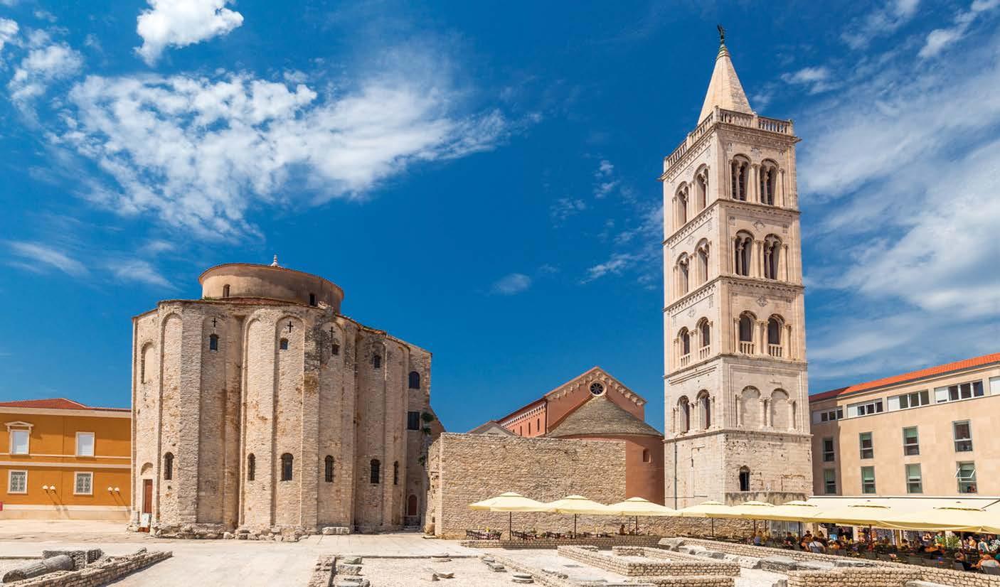
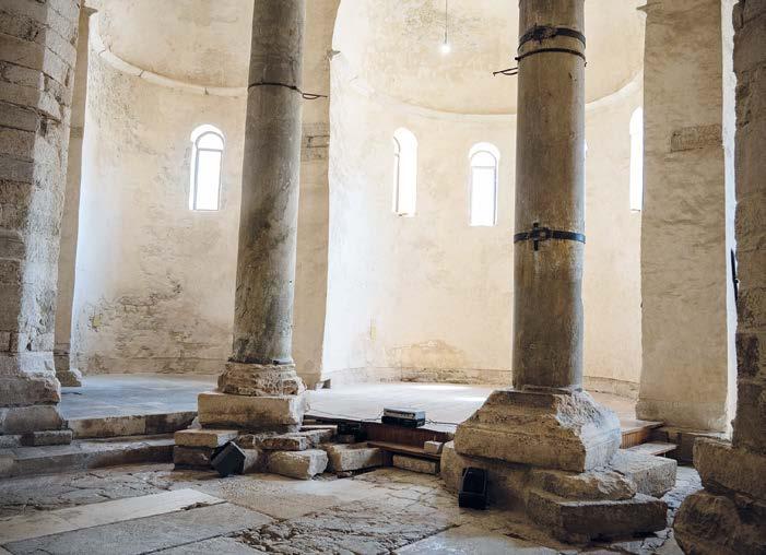
MCI® technology by Cortec® was applied in the restoration of historic structures in Croatia, including the Church of St. Donatus in Zadar and the medieval fortress walls of Ilok, providing corrosion inhibition for reinforced concrete and masonry exposed to moisture and chloride-induced degradation, and contributing to extended service life and structural durability.
Saint Donatus, the symbol of the city of Zadar, Croatia, is classified among the most famous and valuable monuments in Europe. Due to its unique cylindrical appearance and robust monumentality, it is one of the most significant European pre-Romanesque churches. As a protected cultural heritage site, it is listed in the Register of Cultural Goods of the Republic of Croatia and is under UNESCO protection. However, as a result of numerous factors, this valuable monument required urgent rehabilitation.
3D scanning analysis determined that the most critical issues were the church walls, the main structure, and the roof. Historically, between 1927 and 1930, the stability of the foundation was compromised, leading to the implementation of a reinforced concrete support structure under the roof on the south side, which connects the church’s outer and inner rings.
The reinforced concrete structure supporting the Church of St. Donatus was seriously threatened by moisture penetration and corrosive sea spray affecting the medieval monument. A repair project was initiated and Cortec’s MCI® 2020 inhibitor was specified as coating to protect support structure against corrosion. MCI® 2020 is a surface applied corrosion inhibitor designed to migrate through even the densest concrete structures and seek out the steel reinforcement bars in concrete. Even when not in direct contact with metal, the product will migrate through concrete to provide full protection. This environmentally safe inhibitor stops further corrosion of reinforcing metals, significantly extending the service life of the structure.
Renovation of medieval city walls of town of Ilok
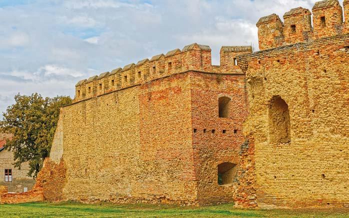
The town of Ilok, Croatia, is a place steeped in rich history and cultural heritage. Its medieval fortress walls and royal castle are protected historical treasures, allowing visitors to truly step back in time. The tower walls have a square floor plan and rest on foundations made of broken stone. These walls are exposed to damaging atmospheric influences; over time, the mortar between the bricks has washed away, leading to the deterioration of the masonry. Restoration work on ‘Tower Three’ included strengthening the foundations, rebuilding collapsed sections, and injecting cracks to restore structural integrity. The project involved the use of corrosion inhibitors to prolong the life of the structure. MCI®-2005 was added to a new concrete foundation being used to support the old foundation. Special attention was given to protecting reinforcing metals in the concrete because of the new foundation’s contact with the soil. Rather than using stainless steel reinforcement, the project opted for black steel reinforcement plus MCI®-2005. MCI®-2018 was applied to brick walls.
As a Migrating Corrosion Inhibitor™ admixture, MCI®-2005 protects embedded metal reinforcement in the new concrete supporting the foundations. MCI®-2018 functions as a water repellent to help protect bricks and mortar from the effects of outdoor weather. Both products were simple additions to significantly improve the longevity of the restoration project without changing the structure’s appearance.
MCI®-2005 is a USDA Certified Biobased Product. By integrating advanced MCI® technology into these historic restorations, Cortec® ensures that Europe’s cultural treasures are not only repaired for today, but sustainably preserved for generations to come. ‹
Moisture penetrating into the medieval monument, combined with airborne sea salt, poses a serious threat to the reinforced concrete structure that supports the Church of St. Donatus
Excavation and preparation for strengthening the medieval city wall foundations, featuring a new concrete foundation enhanced with Cortec's MCI®-2005 to support the historic structures.
Meghna PVC Limited strengthens reliability and steel integrity through proactive corrosion management
Meghna PVC Limited,
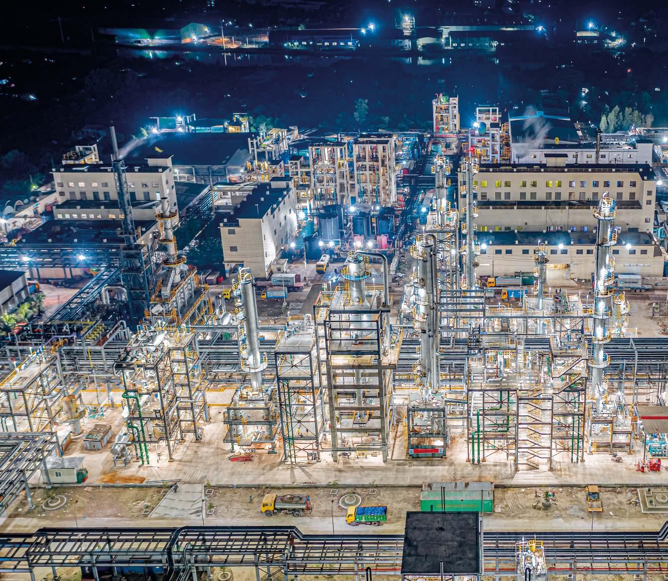
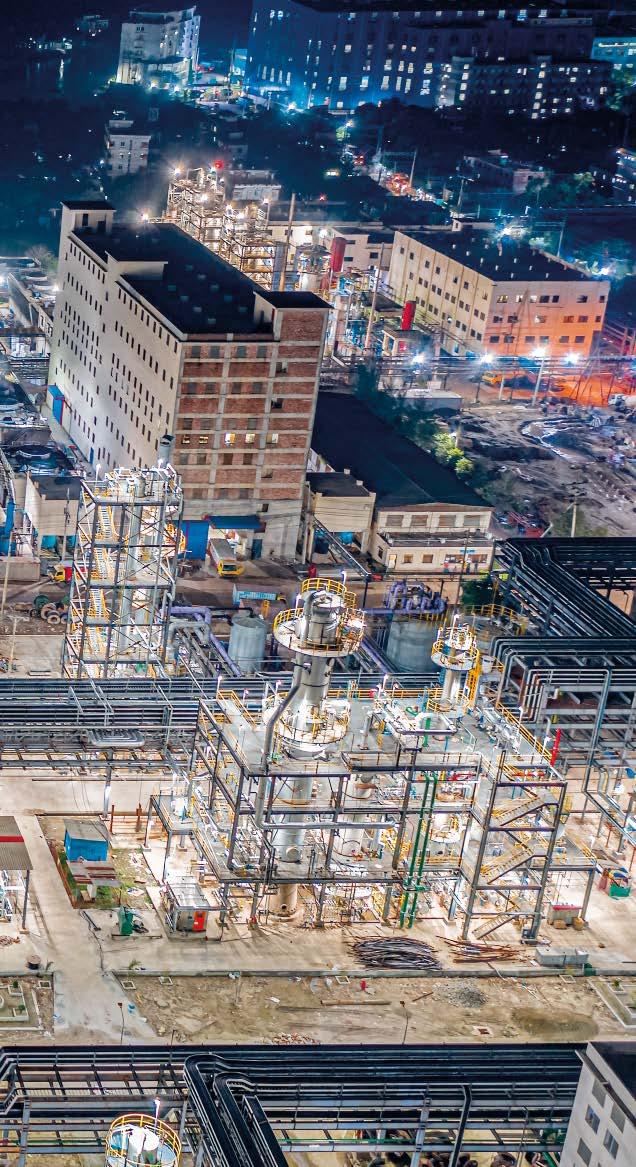
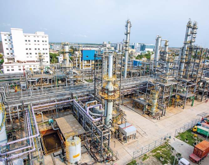
a key company within Meghna Group of Industries (MGI), has taken a decisive step to reinforce long-term steel integrity by adopting a structured, data-driven approach to proactively maintain their assets through a partnership with Jotun.
Operating under extremely aggressive conditions typical of chemical-processing facilities — where corrosion can accelerate rapidly and compromise critical structures — Meghna PVC Limited has demonstrated strong leadership by prioritising preventive action over reactive repairs, using Jotun’s AssetKeeper.
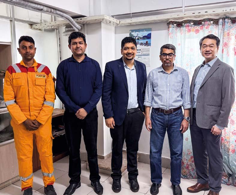
“Meghna PVC Limited partnered with Jotun to implement AssetKeeper, a comprehensive three steps services that designed to optimise maintenance planning and enhance corrosion protection, thus supporting asset owners to establish a long term maintenance strategy” said Sunny Gwee, Managing Director of Jotun Bangladesh ltd., one of the leading paint and coatings manufacturers worldwide.
Jotun have developed the solution to provide a systematic assessment and maintenance plan. This enables sites to identify risk areas sooner, justify maintenance budgets with confidence, and plan interventions before corrosion escalates into costly damage, unplanned downtime, or safety incidents. Through the solution, Meghna PVC Limited is setting a benchmark for responsible industrial risk management in Bangladesh’s manufacturing sector.
“AssetKeeper gave us a clear view of our asset condition and helped prioritise maintenance more effectively. Jotun’s insights will support better planning and long-term protection of our facilities,” said Mohammad Iqbal, Deputy General Manager, Meghna PVC Limited. “Our focus is on protecting people, operations, and the integrity of the facility — and this approach supports all three.”
Corrosion is costing the global economy over USD 2.5 trillion annually, and by 2030 it is estimated that up to 9.1% of global CO2 emissions will originate from steel production only to replace corroded steel. Being proactive and maintaining steel integrity is therefore of high importance for the global environment as well, and we are reliant on responsible stakeholders like MGI.
left to
The initiative includes a detailed condition assessment of existing coatings, a maintenance prioritisation report, and recommendations covering repair strategies and optimised coating systems. Critically, Meghna PVC Limited has also committed to ongoing, yearly assessments to monitor coating performance and support continuous improvement in asset management — an important signal of long-term intent and accountability.
“Meghna PVC Limited’s commitment to safety and steel integrity is exactly the kind of leadership that drives sustainable industrial performance,” said Ashibul Hussain, Segment Manager Marine and Protective in Jotun Bangladesh. “By investing in structured assessment and long-term planning, they’re actively reducing risk and raising the bar for responsible maintenance practices.” The scope encompasses comprehensive maintenance of the entire factory infrastructure, including steel structures and pipeholding systems.
MGI is among Bangladesh’s largest industrial conglomerates, operating more than 57 industrial units and employing tens of thousands of people nationwide. Meghna PVC Limited is the sole manufacturer of PVC and PET in Bangladesh.
“Corrosion is costing the global economy over USD 2.5 trillion annually, and by 2030 it is estimated that up to 9.1% of global CO₂ emissions will originate from steel production only to replace corroded steel. Being proactive and maintaining steel integrity is therefore of high importance for the global environment as well, and we are reliant on responsible stakeholders like MGI,” concludes Ekaterina Mezhentseva, Global Solution Manager in Jotun. ‹
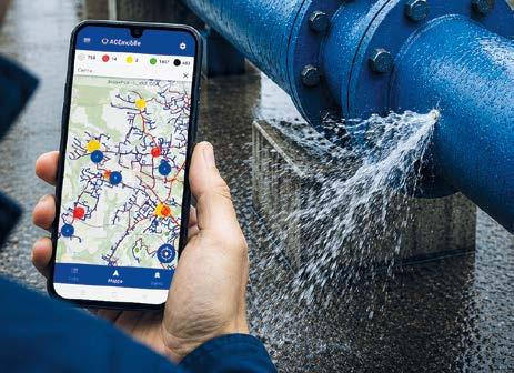
DIGITALISATION IS BECOMING ESSENTIAL FOR THE EFFICIENT AND SUSTAINABLE MANAGEMENT OF WATER NETWORKS. ONYAX, AN ITALIAN COMPANY SPECIALIZED IN TELECOMMUNICATIONS, TELEMETRY AND DATA TRANSMISSION, DEVELOPS IOT AND AI-BASED SOLUTIONS FOR ADVANCED CATHODIC PROTECTION MONITORING. THROUGH THE EVALD PROJECT, IN COLLABORATION WITH POLITECNICO DI MILANO, IT INTRODUCES A PREDICTIVE APPROACH BASED ON DIGITAL TWINS AND INTEGRATED DATA ANALYSIS. AN ECOSYSTEM THAT TURNS MONITORING INTO A CONTINUOUS AND INTELLIGENT PROCESS.
In recent years, the water network sector has had to deal with complex challenges that are requiring significant investments in maintenance and modernization. Cathodic protection continues to represent an effective tool for preserving the integrity of underground infrastructures, counteracting corrosive phenomena that may compromise their safety.
ONYAX’s activity fits into this direction. ONYAX is an Italian company with experience in the field of telecommunications, telemetry and data transmission. Starting from these skills, ONYAX has built a digital ecosystem dedicated to the predictive maintenance of plants.
The objective is to transform corrosion monitoring from an inspection-based and periodic activity into a continuous process supported by Artificial Intelligence. This vision finds its expression in the EVALD project (Electro-Vibro-Acoustic Leakage Detection), developed in collaboration with the Department of Electronics, Information and Bioengineering of Politecnico di Milano, to integrate cathodic protection monitoring with advanced leak detection and predictive analysis technologies.
THE ONYAX DIGITAL ECOSYSTEM
In cathodic protection, data represents the most relevant element. Historically, the collection of this information has been entrusted to periodic manual measurement campaigns, which
present certain limitations: reduced measurement frequency, high operating costs and the impossibility of observing dynamic phenomena. ONYAX has therefore developed an integrated system composed of IoT devices and a cloud platform capable of collecting, processing and transforming large amounts of data into immediately available operational information1 The IoT devices installed in the field are characterized by compact dimensions, integrated battery and ease of installation, making it possible to increase the number of monitored points. The ACE cloud platform uses HTTPS/MQTTS communication protocols with end-to-end encryption, to ensure high levels of security during the transmission of information and to significantly reduce the risks associated with remote data management.
THE EVALD PROJECT
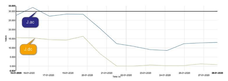
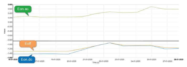
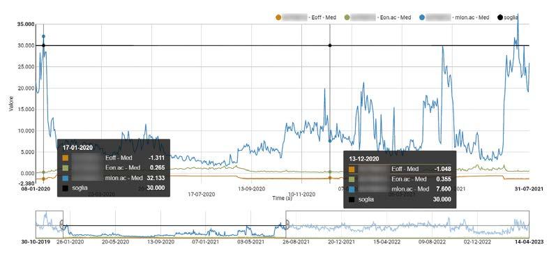
Leak reduction represents one of the main priorities for water network operators. According to the most recent estimates, a significant share of the water introduced into infrastructures is lost before reaching the final user, with relevant economic and environmental consequences. When speaking about cathodic protection, there is a tendency to consider it as a tool for corrosion prevention. In reality, the electrical parameters monitored on infrastructures constitute a source of information on the overall behaviour of the network. Variations in potentials, changes in protection currents or alterations in electrical transients may represent indirect signals of structural changes or anomalous operating conditions.
ONYAX has progressively expanded its approach to monitoring, moving from the simple acquisition of cathodic protection parameters to an integrated model based on the correlation of different physical quantities. The EVALD solution (Electro-VibroAcoustic Leakage Detection) is based on the belief that the data collected can provide much broader information than the sole evaluation of corrosive phenomena, and with the objective of building an always up-to-date digital representation of the network.
ELECTRO-VIBRO-ACOUSTIC APPROACH: BEYOND TRADITIONAL LEAK DETECTION
In most conventional systems, leak localization and the propagation of the acoustic signal can be influenced by the pipe material, ground conditions, operating pressure, the presence of users and numerous external noise sources that may generate false alarms or make the identification of anomalies more complex.
1 IoT and AI for Cathodic Protection: how Onyax solutions optimize remote anti-corrosion monitoring, Corrosion Protection, January 2026 (https://www.ipcm.it/en/open/corrosion-protection/2026/13/19-23.aspx)
The EVALD project aims to overcome these limits through a methodology that actively intervenes by generating controlled signals and simultaneously acquiring different types of information. A structural variation due to corrosion, an emerging leak or localized deterioration may manifest simultaneously through changes in electrical parameters, vibrational variations, alterations in the acoustic response and changes in pressure conditions. By analysing these phenomena in an integrated manner, it becomes possible to obtain a deeper understanding of the real state of the infrastructure and increase the reliability of the analyses.
BLACKBOX-XL-EVA: THE EVOLUTION OF ELECTRICAL MONITORING
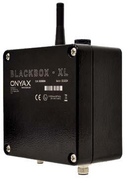
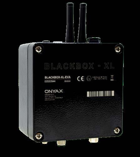
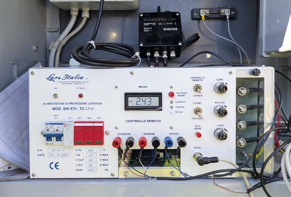
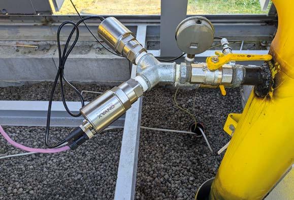
BLACKBOX-XL-EVA is one of the components of the EVALD solution: an IoT device developed to integrate cathodic protection monitoring within an advanced predictive maintenance system with the dynamic analysis of electrical phenomena. The device is installed near the infrastructures to be monitored and can also be connected directly to cathodic protection power supplies. This configuration makes it possible to acquire the parameters normally used to verify the effectiveness of cathodic protection, perform remote regulation and generate high-speed electrical transients.
Temporary variations in electrical quantities can provide valuable information on the behaviour of the structure and its evolution over time. Apparently minimal changes can be interpreted as early indicators of degradation phenomena or structural changes.
TUBE-EVA-TX AND TUBE-EVA-RX: THE ACOUSTIC AND VIBRATIONAL ANALYSIS OF THE NETWORK
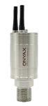
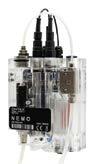
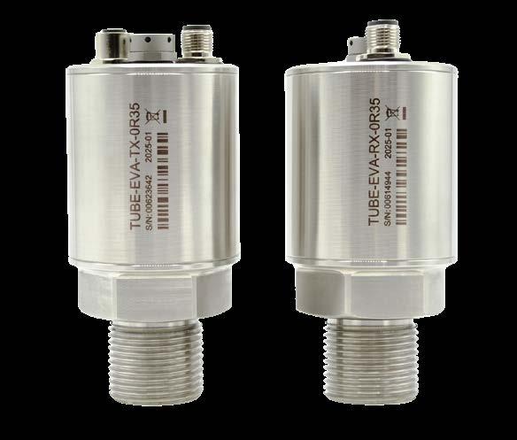
Alongside the electrical analysis operates the vibro-acoustic component, entrusted to the TUBE-EVA-TX and TUBE-EVA-RX sensors. These units, designed to monitor the physical behaviour of the network, collect information that normally escapes traditional control methodologies.
TUBE-EVA-TX acts as a transmitter and enables the controlled injection of sound signals inside the pipeline. Through this operation, the system generates an artificial and perfectly known source, which can then be detected and analysed along different points of the network.
TUBE-EVA-RX, on the other hand, is dedicated to signal acquisition and integrates an advanced detection system equipped with a hydrophone. In addition to acoustic information, the device simultaneously monitors pressure, fluid temperature and vibrations on multiple axes.
The presence of these different quantities makes it possible to evaluate the way in which the signal propagates along the network, verifying frequency variations and correlations with the other acquired parameters.
BLACKBOX-XL-EVA device.
TUBE-EVA sensors.
THE DIGITAL TWIN OF THE NETWORK
To achieve the ability to transform the information collected into operational knowledge, Politecnico di Milano has developed an advanced Artificial Intelligence component aimed at creating the Digital Twin of the network.
The digital twin represents a virtual replica of the real infrastructure, built starting from the data collected by IoT devices and continuously updated through new measurements. Each piece of information coming from the field contributes to enriching the digital model, allowing it to progressively learn the specific behaviour of the monitored network.
The Digital Twin evolves over time and becomes increasingly accurate as the amount of available data increases.
ACE: FROM DATA COLLECTION TO DECISION-MAKING SUPPORT
All data acquired by the IoT devices is transmitted to the ACE platform, where it is integrated, historized and correlated. The information collected constantly feeds the Digital Twin of the network and allows Artificial Intelligence algorithms to progressively refine the analysis and prediction models.
Thanks to the use of Machine Learning and Deep Learning algorithms, ACE continuously processes the data coming from the field, comparing it with the historical measurements and identifying patterns, anomalies and possible evolutions of the infrastructure’s condition.
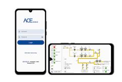
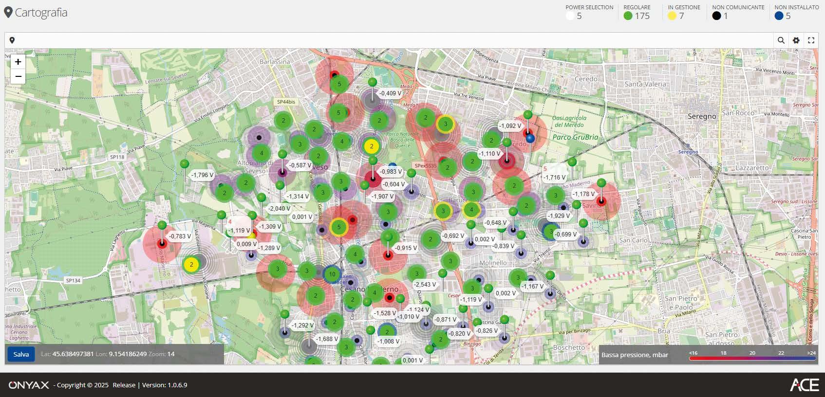
The results of the analyses are returned to operators through intuitive dashboards and interactive maps that make it possible to visualize the state of the network in real time, monitor the trend of the acquired parameters and identify the areas characterized by a higher probability of leakage or possible degradation phenomena. In this way, raw data is transformed into operational information that can be immediately used to plan inspections, optimize interventions and improve management efficiency.
A further distinctive element of the platform is its high scalability. The same architecture is in fact capable of managing from a few dozen to tens of thousands of monitoring points distributed across networks of any size. Furthermore, the possibility of integration with third-party GIS and SCADA systems allows operators to insert ONYAX technologies within their own digital ecosystems.
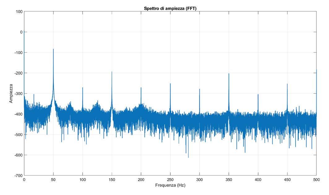
“Amplitude Spectrum” screen on ACE platform.
THE CASE STUDY
To validate the effectiveness of the EVALD solution in real operating conditions, ONYAX has launched a trial with an important company belonging to the A2A Group. The challenge consists in identifying the areas with the highest probability of leakage within a network extending for approximately 90 km, with the objective of supporting the
planning of targeted inspection campaigns and reducing the number of unnecessary checks.
After an initial phase of development and validation in the laboratory, the technology was installed in two municipalities in the province of Monza and Brianza, making it possible to collect real data and verify in the field the behaviour of the algorithms developed.
“Cartography” screen with a network leaks map on ACE platform.
An example of a BLACKBOX-XL-EVA device installation.
An example of a TUBE-EVA device installation.
One of the most relevant aspects of the trial concerns precisely the reduction of false positives. The multidisciplinary approach adopted by EVALD aims to progressively improve the reliability of the analyses through the correlation between different types of data and the continuous training of the Digital Twin.
The final objective is to allow operators to concentrate their activities in the truly critical areas, reducing intervention times, operating costs and environmental impact.
Towards a new generation of digitized infrastructures
The evolution of networks inevitably passes through digitalization. In a context characterized by increasingly extensive and complex infrastructures, the availability of continuous and reliable information in fact represents the key to guaranteeing sustainability and operational efficiency.
With the EVALD project, ONYAX proposes an innovative vision in which cathodic protection, IoT monitoring, Artificial Intelligence and Digital Twin converge within a single technological ecosystem. ‹
BY COMBINING REAL FIELD DATA, AI ALGORITHMS AND DIGITAL TWIN TECHNOLOGY, EVALD ENABLES OPERATORS TO FOCUS INSPECTIONS WHERE LEAKS ARE MOST LIKELY TO OCCUR, REDUCING FALSE POSITIVES AND OPERATIONAL COSTS.
EVALD COMBINES AI AND DIGITAL TWIN TECHNOLOGY TO REDUCE FALSE POSITIVES AND OPTIMISE INSPECTIONS.
IBIX SURFACE PREPARATION AND FLAME SPRAY TECHNOLOGY
for long-term anti-corrosion and waterproofing thermoplastic coatings (anti-osmotic protection, electrical insulation, chemical resistance)
Temperature resistance from -40°C to +70°C approx
Resistance to extreme weathering, UV and salt spray protection
Immediate use of coated items
Easy to repair
PHC-A
C5 - lm3 to ISO 12944-9
PHC-PLUS CX - lm4 to ISO 12944-9
Ilaria Paolomelo, ipcm®
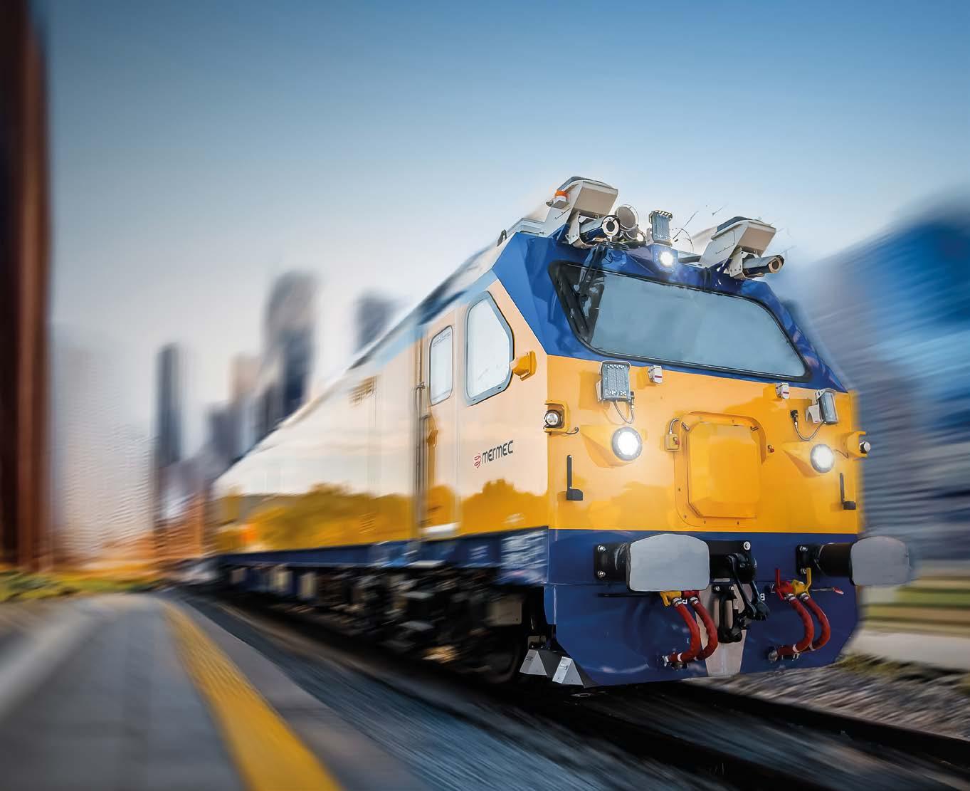
Diagnostic trains are now a strategic component of the modern railway ecosystem, enabling continuous, highprecision monitoring of infrastructure conditions. They are highly specialised vehicles equipped with advanced measurement systems, including lasers, inertial sensors, optical systems, and highfrequency data acquisition units, which analyse key parameters in real time, such as track geometry, rail wear, contact line conditions, and overall network integrity.
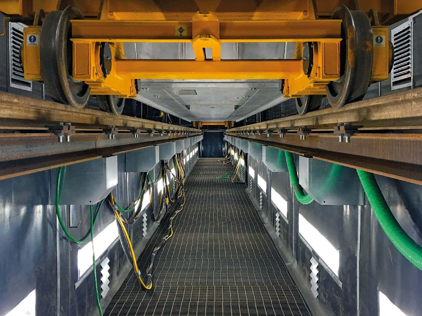
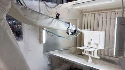
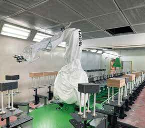
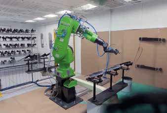
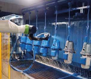
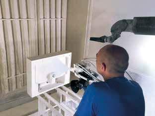
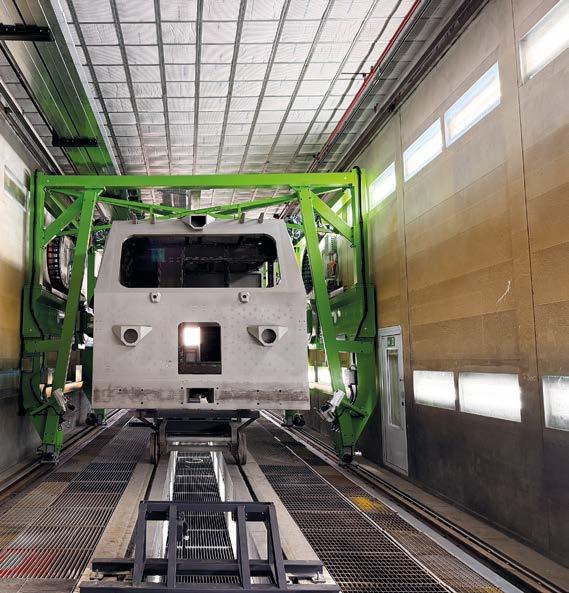
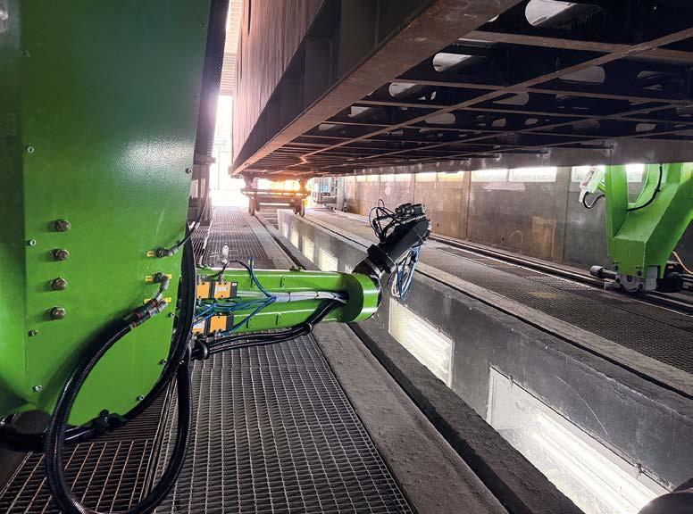
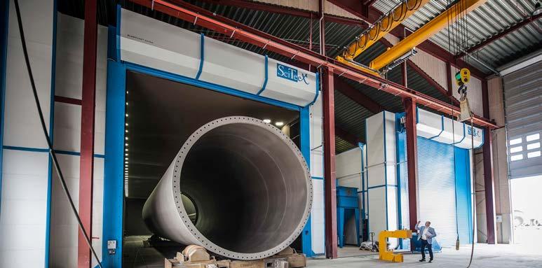
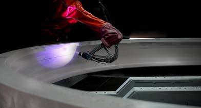
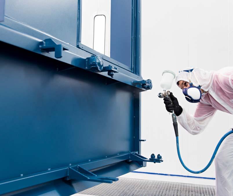
Integrating robotics into an existing paint booth and automating the coating of a railway vehicle measuring about 25 metres in length has required a bespoke solution: for MERMEC Ferrosud, CMA Robotics developed a system based on two 9-axis GR6150 articulated robots, ensuring high operational flexibility, improved process repeatability, and consistent coating quality.
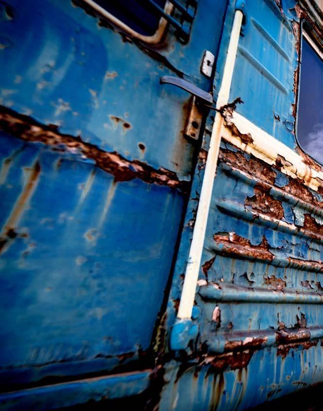
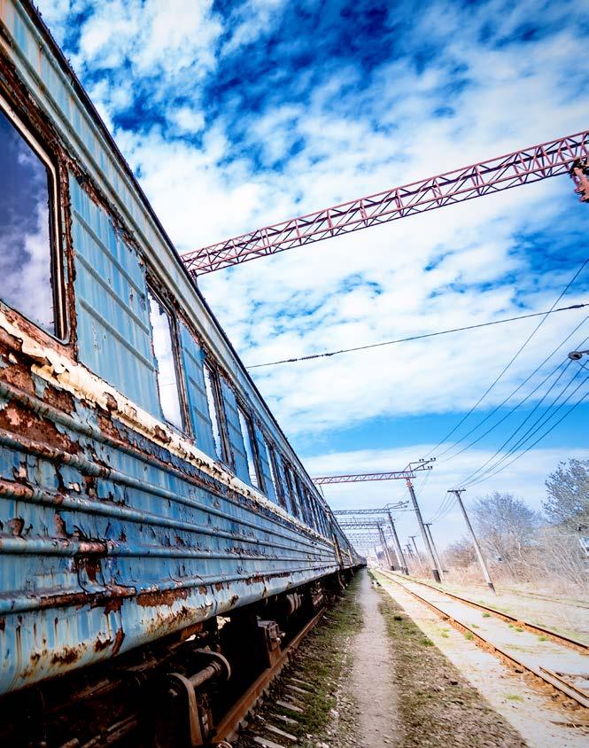
Their development aligns with the paradigm of predictive maintenance, which relies on the systematic collection and analysis of data to anticipate signs of deterioration and plan targeted interventions. The reliability of diagnostic trains is therefore a critical factor: any reduction in instrument accuracy or vehicle availability can have direct consequences for the safety and operational continuity of the railway network. Alongside the technological complexity of the on-board systems, a fundamental role is played by the structure of the train itself and, above all, by the protection of the carbody. During their service life, these vehicles are indeed subjected to highly variable environmental conditions, characterised by temperature fluctuations, humidity, rain, atmospheric contaminants, and abrasive dust. These conditions can trigger corrosive reactions that progressively compromise metal surfaces, with both aesthetic and structural consequences. Processes such as electrochemical corrosion, accelerated oxidation, and corrosion under coating can lead to material loss, weakened joints, and increased maintenance costs. That is why the choice of high-performance industrial coating systems is key to ensuring the durability of the protective layer, limiting corrosion, and preserving the reliability of the rolling stock throughout its life cycle. These requirements formed the basis
for the investment made by MERMEC Ferrosud (Matera, Italy) to install two articulated robots from CMA Robotics (Pavia di Udine, Italy) for coating the bodies of its diagnostic trains. This system has been integrated into an existing 30-metrelong booth to increase production capacity, improve coating quality, and ensure greater process repeatability.
Two industrial stories converge: the founding of MERMEC Ferrosud MERMEC Ferrosud’s industrial origins stem from the convergence of two distinct backgrounds: MERMEC S.p.A., a company specialising in railway diagnostics and signalling, and Ferrosud, a factory established to manufacture railway vehicles. “The former was founded in the 1960s as Meridional Meccanica, initially a Lamborghini Trattori dealership. The decisive turning point came in the 1980s, when it entered the railway sector and began designing and manufacturing vehicles for track maintenance. In 1988, it became a public limited company, and over the following decade it developed and patented its first diagnostic train, an autonomous railway vehicle capable of monitoring infrastructure condition and detecting defects and micro-cracks measuring just a few millimetres, even at speeds of 300 km/h,” says Sante Cammisa, Investments and Special Projects at MERMEC Ferrosud.
The Ferrosud plant, founded in 1963 as part of an industrial development programme for Southern Italy, saw its history unfold around the same time. Over the years, it underwent several corporate changes, becoming part of Breda Ferroviaria in 1980 and of AnsaldoBreda in 1992. Following privatisation in 2002, Ferrosud entered a difficult period that led to a gradual reduction in production, until the turn of events in October 2022, when MERMEC acquired it and embarked on a path of industrial revitalisation.
This marked the birth of present-day MERMEC Ferrosud, which resumed operations in mid-2023 after an urgent redevelopment phase. “We had to restore everything essential to get operations up and running again, from the extraction and lighting systems to the most severely affected production areas. Only then did we launch an investment plan to modernise the factory’s technology. We implemented several new automated solutions, including the two GR-6150 coating robots from CMA Robotics.”
A state-of-the-art industrial hub for the manufacture of diagnostic trains
The MERMEC Ferrosud facility is now one of the largest railway manufacturing hubs in Europe, with a total area of about 230,000 m², of which 55,000 m² are covered. The facility features a highly specialised internal infrastructure, including 1.4 km of track and a direct rail link to the national network, enabling the movement and dispatch of rolling stock without special road transport. “This plant was designed to handle large-scale railway products and complex production flows. Here we can build a complete train, from the metal carbody to the powered and trailing bogies, while our parent company, MERMEC S.p.A., supplies the diagnostic systems that are subsequently installed and integrated into the vehicle,” explains Cammisa.
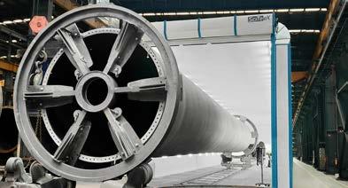
The metal carbodies, the vehicles’ main load-bearing structures, and the powered and trailing bogies designed to support the rolling stock are manufactured in the metalworking department, which covers around 8,000 m². After machining and welding, the bodies are taken via a transfer car to the automated shot blasting booth, where oxides, scale, and surface contaminants are removed, and then to one of two 30-metre-long booths devoted to finishing the rolling stock bodies. The robotic system developed by CMA Robotics is installed in one of them.
Downstream of the coating process, the car bodies move to the final assembly department, a space of approximately 6,500 m² equipped with four parallel railway tracks, where they are coupled with their respective bogies, previously processed in dedicated departments. The production cycle ends with quality controls and functional tests, including dimensional and geometric checks
At present, the robots handle the application of the anti-rust primer, the acrylic primer, and the top coat. They are each equipped with three coating guns assigned to the different products, but they are designed to accommodate a fourth gun for applying the epoxy filler if required in the future.
of the welded structures, roughness checks after shot blasting, measurements of paint film thickness, and verification of the coatings’ characteristics. In addition, tests are carried out on the complete vehicle, including brake tests, electrical checks, and watertightness tests under simulated rain conditions.
The coating cycle
In the coating booth that was the subject of the recent investment, MERMEC Ferrosud applies a multi-layer coating system comprising four main products: an anti-rust primer, an epoxy filler, a sandable acrylic primer, and a polyurethane top coat. The process begins with the application of the anti-rust primer using the CMA robots, followed by a drying phase in the oven. The epoxy filler is then applied manually to level and prepare the surface before the sanding stage. Once this process is complete, the body undergoes automated application of the sandable acrylic primer and, afterwards, the polyurethane top coat. Both stages are followed by an oven-drying phase, necessary to ensure the coating stabilises correctly and the protective system achieves its final performance characteristics.
“At present, the robots handle the application of the anti-rust primer, the acrylic primer, and the top coat. They are each equipped with three coating guns assigned to the different products, but they are designed to accommodate a fourth gun for applying the epoxy filler if required in the future. For now, we have chosen to continue applying the filler manually because we believe the operator’s
experience still ensures optimal control over surface levelling and overall results,” indicates Cammisa. “The carbody coating process ends with the application of an intumescent paint, a fire-retardant product currently applied manually to the underbody of the railway vehicles and to interior areas. As these are diagnostic trains rather than passenger trains, their interiors contain a great deal of equipment, including batteries, servers, computers, and electrical systems, which require specialised protection,” adds.
Designing a robotic system for an existing booth
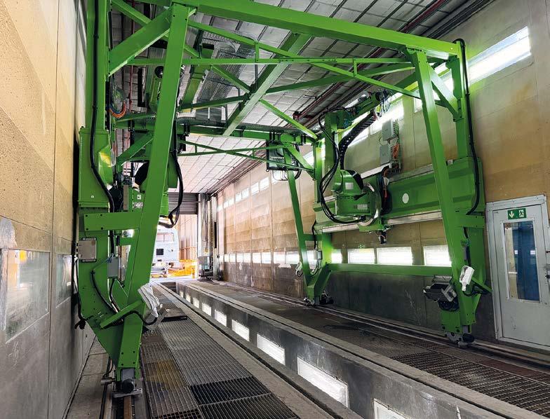
Integrating the robotic system posed a significant design challenge, as the solution developed by CMA Robotics had to be fitted into an existing coating booth dating back to the 1970s, which had been revamped in 2023 to meet current safety standards and regulations. “The unique aspect of this project was the need to work on an existing structure, for which not all the original design documents were available. For this reason, we carried out detailed surveys and reconstructed the entire booth in a CAD environment, so as to develop a solution that would integrate perfectly into the available space,” explains Marco Zanor, CEO of CMA Robotics. Based on the plant’s digital model, the company developed a bespoke system for installation within the existing booth, including
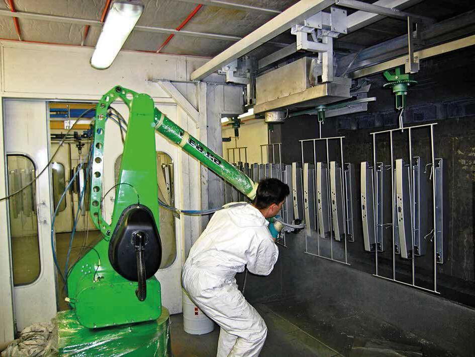
a metal gantry and robotic equipment, without altering the plant’s original configuration. The two articulated robots were mounted on the right and left sides of the gantry, designed to operate in coordination along the entire length of the carbody. Each robot is mounted on a traversing slide that enables it to move within the metal structure and reach all surface areas to be coated. “The robot can move along a linear axis, allowing it to move along the gantry, while a dedicated slewing ring enables the rotation of the entire robotic unit, significantly expanding its working envelope.
This configuration allows coating not only the entire length of the railway vehicle, normally approximately 25 metres, but also the upper and lower surfaces of the carbody, including the roof and the underframe,” says Zanor.
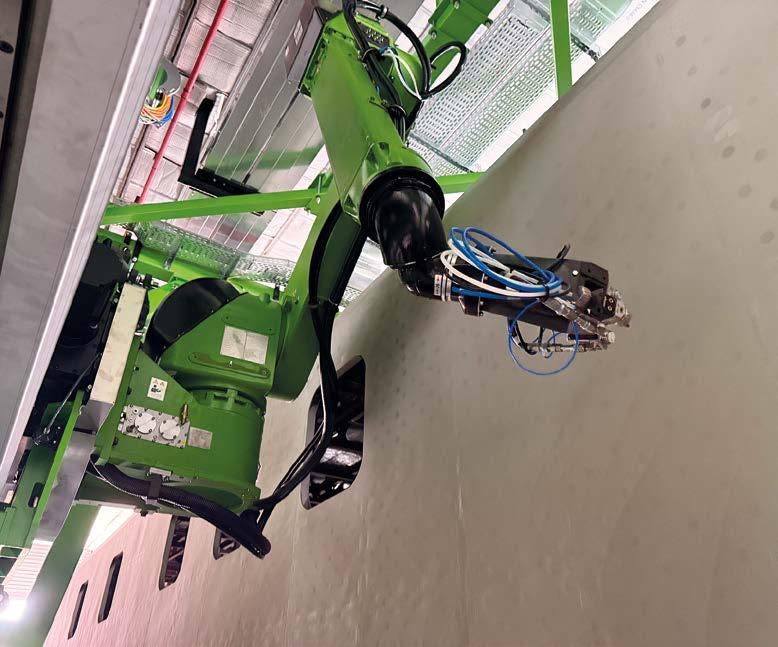
“The robots can also operate in an inverted position, a solution developed specifically to achieve greater vertical reach and access even the most complex geometries of the vehicles.” This improves access to the most critical areas and enables a more uniform coating of the entire surface of the rolling stock, without the need for additional vehicle movement or specialised equipment. “The ability to automatically reach even the uppermost parts of the carbody has, in fact, enabled us to reduce the use of equipment for working at height, significantly improving safety and ergonomics for our operators,” notes Cammisa.
In the coating booth, MERMEC Ferrosud uses robots to apply an anti-rust primer, a sandable acrylic primer, and a polyurethane top coat. On the left, the metal gantry equipped with two 9-axis GR-6150 articulated robots from CMA Robotics.
“To speak simply of an additional axis would be an oversimplification, because the system integrates multiple coordinated movements: in addition to the six axes of the articulated robot, there is a seventh linear axis enabling movement along the entire length of the booth, an eighth axis consisting of the slewing ring rotation, which extends the robot’s range, and a further motion axis that further expands the system’s overall working envelope,” says Daniele Donato, project manager at CMA Robotics. Another distinctive feature concerns the system for detecting the position of the workpieces within the booth. The carbody is moved by a temporary transfer car used exclusively for internal handling between production departments: CMA Robotics has used this equipment as a reference for automatic positioning, integrating a limit switch unit that, once it has detected that the transfer car has entered the booth correctly, sends an enable signal to the control software to start the coating cycle.
A successful partnership for the evolution of coating processes
The decision to partner with CMA Robotics stemmed from the need to support MERMEC Ferrosud’s growth by engaging a technology partner with experience, reliability, and design expertise in automating coating processes. “With the acquisition of this facility, we began handling a completely different volume of orders than before. Given its strategic importance, we therefore needed to innovate the coating process, and we could not afford to entrust such a complex project to partners lacking the necessary experience,” says Cammisa. The choice was also backed by endorsements from the other partners in the project, including the suppliers of the paint products and the mixing system. Indeed, the project went beyond installing robots to integrating various technologies into the existing booth. “The automation devices, the paint management equipment, and all the existing systems had to be harmonised. CMA also supported us in identifying technical solutions beyond the scope of its own supply, demonstrating a great capacity for collaboration,” emphasises Cammisa. Although the system is still in the final testing phase, initial feedback has been extremely positive.
“The automation solutions, along with the new paint mixing unit, ensure greater control over material consumption and waste, more consistent management of application parameters, and more uniform coatings compared with manual processes.”
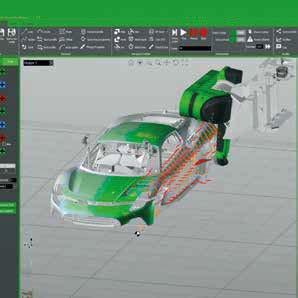
A further advantage is process repeatability. Using CMA Robotics’ Efort Paint Studio offline programming software, application patterns can be defined and reproduced with a high degree of precision, ensuring consistency even in future production runs involving vehicles with different configurations or multiple carbodies. Finally, the introduction of this new technology also constituted an investment in human capital. “We are training technicians and operators in the management, programming, and testing of the robotic cell. Our goal is not merely to introduce a new machine, but to develop in-house expertise that will enable us to fully exploit this technology’s potential,” states Cammisa.
In the final commissioning phase, the technical teams from MERMEC Ferrosud and CMA Robotics are now defining and optimising the coating programmes by configuring the application patterns and finetuning the process parameters for the various surfaces of the railway carbodies, in preparation for the plant’s full-scale operation. ‹
A further advantage is process repeatability. Using CMA Robotics’ Efort Paint Studio offline programming software, application patterns can be defined and reproduced with a high degree of precision, ensuring consistency even in future production runs involving vehicles with different configurations or multiple carbodies. Finally, the introduction of this new technology also constituted an investment in human capital.
Stop Corrosion Before It Starts.
VpCI® coatings protect a wide range of metal assets, providing fast and economical preservation for both interior and exterior surfaces. Our technical experts are ready to help you select the ideal solution for long-lasting, complete protection of your corrosion-sensitive products.
SCIENCE OUTLOOK
Optimizing surface-applied zinc anode systems for reinforced concrete infrastructure: lessons from laboratory and field investigations
Hadi Beirami, Ph.D. of Corrosion Engineering, AMPP/NACE-CP4 Cathodic Protection Specialist Trento, Italy - hbeirami@cormit.it
A study based on laboratory tests and field monitoring analyses the effectiveness of adhesive zinc anode systems for the cathodic protection of reinforced concrete, highlighting the role of current distribution capability in system design. The results confirm the reliability of a performancebased approach supported by long-term monitoring.
Surface-applied adhesive zinc anodes are increasingly used for the galvanic cathodic protection of reinforced concrete infrastructure due to their ease of installation and distributed current delivery. However, limited experimentally validated information is available regarding their effective throwing power and its implications for system design. This study combines laboratory investigations and long-term field monitoring to evaluate the relationship between anode throwing power, cathodic protection performance, and practical design considerations. In the laboratory phase, a chloride-contaminated
reinforced concrete slab equipped with a surface-applied adhesive zinc anode and four embedded reference electrodes was monitored for more than two years. The results showed a clear distancedependent attenuation of cathodic polarization and highlighted the existence of a protection gradient rather than a fixed protected/unprotected boundary. Field validation was carried out using monitoring data from the Baells Bridge in Spain, where the same galvanic cathodic protection technology has been operating for more than three years. Recent inspections confirmed depolarization values exceeding 100 mV, demonstrating sustained long-term performance.
The good agreement between laboratory and field observations supports the use of laboratory-derived design parameters for infrastructure applications and highlights the value of a performance-based approach combining laboratory testing, environmental assessment, and long-term monitoring.
Introduction
Corrosion of steel reinforcement remains one of the most significant threats to the durability and serviceability of reinforced concrete infrastructure worldwide. Bridges, tunnels, marine structures, parking facilities, retaining walls, and other critical assets are continuously exposed to aggressive environmental conditions that promote chloride ingress and corrosion initiation. Once the passive film protecting the reinforcing steel is destroyed, corrosion products accumulate around the reinforcement, generating expansive stresses that eventually lead to cracking, delamination, spalling, and progressive structural deterioration. The economic and societal consequences of corrosion-related damage in infrastructure are substantial. In many countries, a significant portion of maintenance budgets is allocated to the repair and rehabilitation of reinforced concrete structures affected by corrosion. Consequently, considerable efforts have been devoted over the past decades to developing effective corrosion mitigation strategies capable of extending service life while minimizing maintenance interventions.
Among the available rehabilitation techniques, cathodic protection (CP) is widely recognized as the only technology capable of reliably stopping ongoing chloride-induced corrosion in reinforced concrete structures, regardless of chloride concentration [1]. Traditionally, cathodic protection systems have been implemented either as impressed current cathodic protection (ICCP) systems or as galvanic cathodic protection systems based on sacrificial anodes. While ICCP systems provide a high degree of controllability and can deliver substantial protection currents, they require external power supplies, monitoring equipment, and periodic maintenance. Galvanic systems, on the other hand, offer a simpler and often more sustainable solution, particularly for atmospheric exposure conditions and structures requiring lowmaintenance operation.
In recent years, significant technological developments have occurred in the field of galvanic cathodic protection of reinforced concrete. New generations of discrete and distributed galvanic anodes have been introduced, together with updated international standards aimed at improving performance verification and long-term durability assessment. In particular, the publication of AMPP SP0216-2023 and AMPP SP21520-2023 has shifted the focus from merely installing galvanic anodes to demonstrating and monitoring their electrochemical performance throughout the service life of the structure [2, 3]. These standards emphasize the importance of measurable protection criteria, depolarization
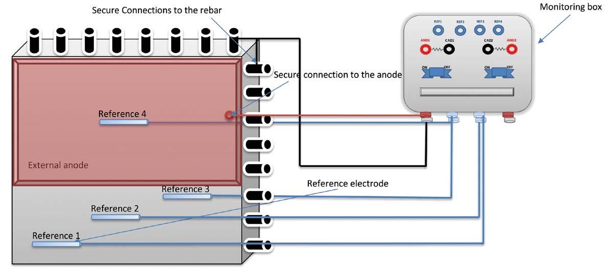
Figure 1 - Schematic representation of the laboratory setup for evaluating the throwing power of the surface-applied adhesive zinc anode.
assessments, current monitoring, and long-term verification of system effectiveness.
Despite these advances, one of the most challenging aspects of galvanic cathodic protection design remains the estimation of anode influence distance, commonly referred to as “throwing power”. Unlike impressed current systems, galvanic systems cannot be adjusted after installation. Consequently, the initial design phase becomes critical, particularly regarding anode spacing, distribution, mass selection, and expected service life. Overestimating throwing power may result in under-protected areas, whereas excessively conservative designs can lead to unnecessary installation costs and reduced economic competitiveness.
To address this gap, the present study combines controlled laboratory investigations with long-term field monitoring of a reinforced concrete bridge protected using surface-applied adhesive zinc anodes. Laboratory testing was conducted on chloride-contaminated reinforced concrete specimens instrumented with multiple embedded reference electrodes positioned at increasing distances from the anode. The electrochemical response was monitored for more than two years in order to quantify the attenuation of cathodic polarization with distance and time. These findings were subsequently compared with monitoring results obtained from a full-scale bridge application in Spain, where the same anode technology has been operating under real environmental conditions for more than three years.
Methodology
Laboratory Investigation
A laboratory program was conducted to evaluate the spatial distribution of cathodic polarization generated by a surfaceapplied adhesive zinc anode and to quantify its effective throwing power under controlled conditions.
A reinforced concrete slab measuring 800 × 800 × 100 mm was prepared and instrumented with a surface-applied adhesive zinc anode installed on one side of the specimen. The reinforcement arrangement was designed with a concrete cover of approximately 40 mm and a steel density ratio close to 0.96. To promote active corrosion conditions, sodium chloride was intentionally incorporated into the concrete mix at a dosage corresponding to approximately 1% chloride by weight of cement.
Four permanent reference electrodes were embedded within the concrete at increasing distances from the anode. One electrode was positioned directly beneath the anode, while the remaining electrodes were installed at distances of 10, 20, and 30 cm from the anode edge. All reference electrodes and electrical connections were routed to an external monitoring box, allowing periodic electrochemical measurements throughout the exposure period (Figure 1).
Potential measurements were performed under both connected (ON) and disconnected (24-hour OFF) conditions. Since the permanent reference electrodes were embedded within the concrete and installed close to the reinforcement, IR-drop effects were considered negligible for the purposes of depolarization assessment.
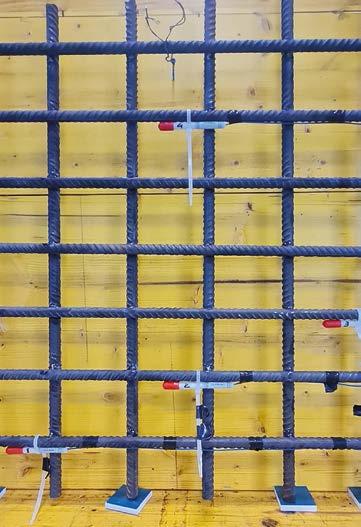
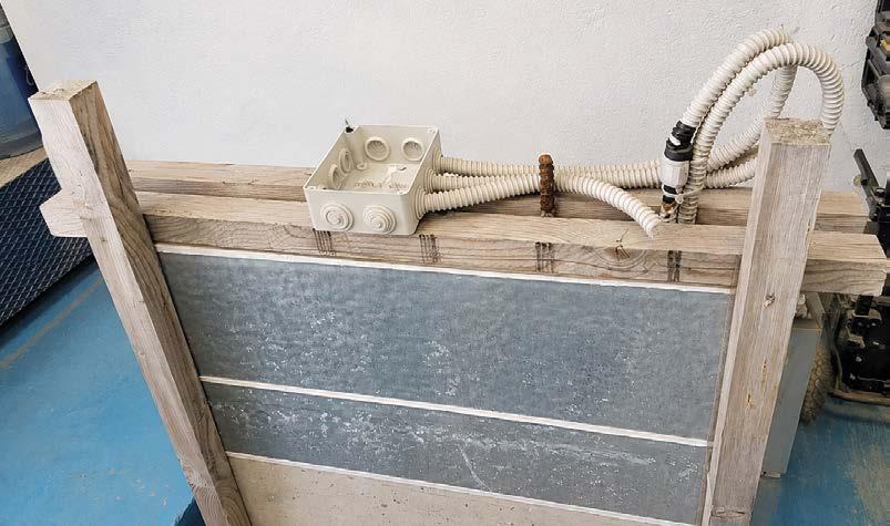
Figures 2a and 2b - Reinforcement arrangement, reference electrode layout (left) and laboratory specimen (right).
The monitoring program extended for more than two years, during which depolarization measurements were periodically recorded. Environmental conditions were also monitored throughout the exposure period. The average temperature during testing was approximately 15°C, with recorded values ranging from 5.9°C to 28.9°C, while relative humidity varied between 40% and 80%. Figure 2 shows the reinforcement cage and the position of the embedded reference electrodes before concrete casting and the prepared sample.
Field validation
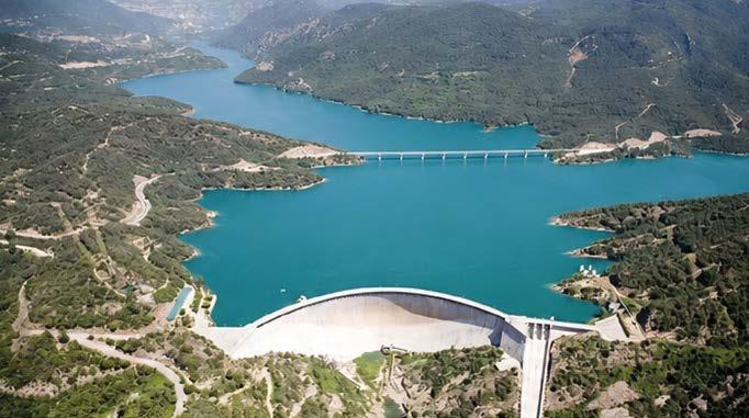
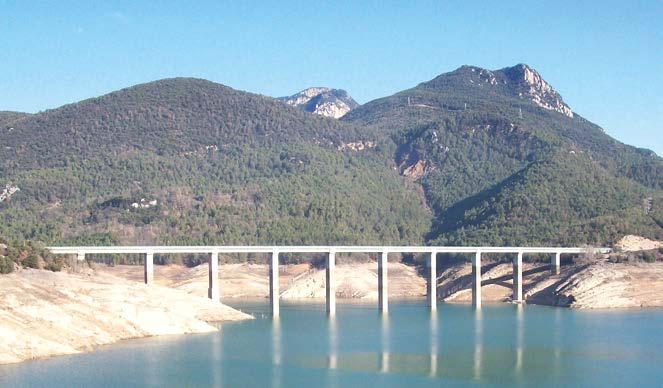
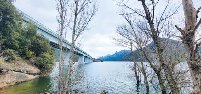
To verify whether the laboratory observations were representative of actual infrastructure performance, a long-term field validation program was conducted on selected piers of the Baells Bridge in Spain. Figure 3 provides an overview of the bridge. The potential mapping based on ASTM C876-15 standard [4] and cathodic protection application were conducted on two specific piers, namely Pier A and Pier B, of the bridge. The bridge was constructed in 1975 and is located in a reservoir environment where the reinforced concrete piers are exposed to cyclic moisture variations and chloride-contaminated conditions.
The cathodic protection system was equipped with embedded reference electrodes and monitoring boxes to facilitate periodic inspections. During each monitoring campaign, ON potentials, instant-OFF potentials, depolarization values, and galvanic current densities were measured. The monitoring program continued for more than three years following installation, providing valuable information regarding the longterm electrochemical performance of the system under real environmental exposure conditions.
Performance assessment was carried out in accordance with ISO 12696:2022, AMPP SP21520-2023, and AMPP SP0216-2023 [2, 3, 5] recommendations for cathodic protection of reinforced concrete structures.
The
cathodic protection system was equipped with embedded reference electrodes and monitoring boxes to facilitate periodic inspections. During each monitoring campaign, ON potentials, instant-OFF potentials, depolarization values, and galvanic current densities were measured. The monitoring program continued for more than three years following installation, providing valuable information regarding the long-term electrochemical performance of the system under real environmental exposure conditions.
Figures 3a and 3b - Overview of the Baells Bridge and selected piers investigated in this study.
PIER A
PIER B
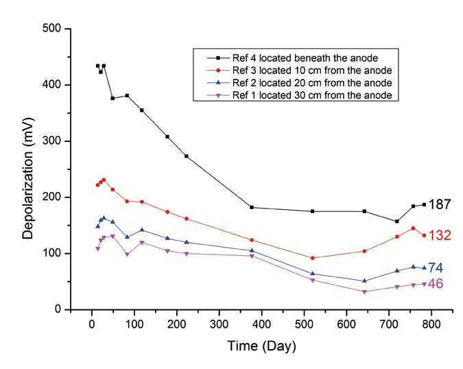
Figure 4 - Evolution of 24-hour depolarization measured at increasing distances from the anode during more than 800 days of exposure.
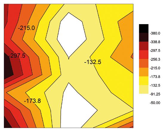
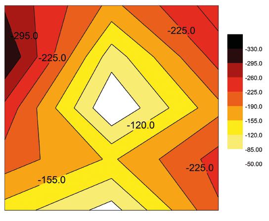
Figures 5a and 5b - Corrosion potential maps of Pier A and Pier B before cathodic protection installation, identifying the most corrosionactive areas selected for long-term performance monitoring.
Result and discussion
Laboratory evaluation of throwing power
One of the main objectives of this study was to quantify the effective influence distance of surface-applied adhesive zinc anodes under controlled laboratory conditions. Understanding how cathodic polarization varies with distance from the anode is essential for optimizing anode spacing and improving the design of galvanic cathodic protection systems for reinforced concrete infrastructure.
Figure 4 shows the evolution of 24-hour depolarization measured at four embedded reference electrodes positioned directly beneath the anode and at distances of 10, 20, and 30 cm from its edge over a monitoring period exceeding 800 days. The results clearly demonstrate a distance-dependent attenuation of cathodic polarization. The highest depolarization values were consistently recorded beneath the anode, while progressively lower values were measured at increasing distances. This behaviour reflects the natural decrease in galvanic current distribution as the distance from the anodic source increases. During the initial exposure period, relatively high depolarization values were observed at all monitoring locations, indicating strong galvanic activity of the freshly installed zinc anode. As exposure time increased, depolarization gradually decreased, suggesting a transition toward a more stable electrochemical condition associated with progressive steel polarization and reduced current demand.
After approximately 800 days, depolarization stabilized at about 187 mV beneath the anode and 137 mV at 10 cm from the anode edge, both exceeding the commonly adopted 100 mV protection criterion [3, 5]. At 20 cm and 30 cm, the measured depolarization values were approximately 74 mV and 46 mV, respectively. These results indicate that surface-applied adhesive zinc anodes can provide effective and sustained polarization within approximately 20 cm from the anode edge under the conditions investigated. Beyond this distance, the protective effect remains detectable but progressively decreases as a function of concrete resistivity, moisture content, chloride contamination, and other environmental factors. Rather than defining a sharp protected/ unprotected boundary, the results reveal the existence of a protection gradient within the concrete.
Long-Term field validation: Baells Bridge case study
The long-term monitoring results obtained from the Baells Bridge provided an opportunity to compare laboratory observations with the performance of the same surface-applied adhesive zinc anode technology under real exposure conditions.
As shown in Figure 5, before installation of the CP system, corrosion potential mapping identified localized areas with a significantly higher probability of active corrosion. These regions were selected as representative locations for monitoring the longterm effectiveness of the cathodic protection system and can be
From left to right:
considered the most demanding exposure conditions within the investigated bridge piers.
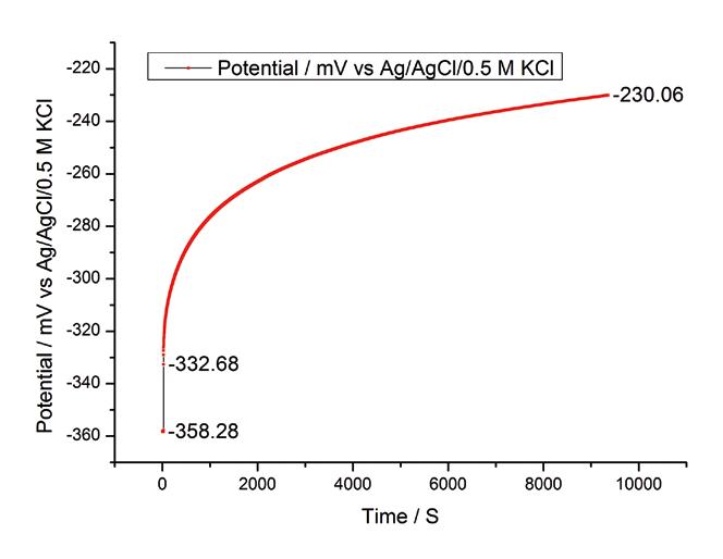
More than three years after installation, the galvanic cathodic protection system continued to provide effective polarization of the reinforcing steel. Figure 6 presents a representative depolarization curve recorded during the most recent monitoring campaign. A depolarization value exceeding 100 mV was achieved within approximately 2.5 hours after circuit interruption, demonstrating compliance with the acceptance criteria defined by ISO 12696 and recent AMPP recommendations.
For Pier B, a reliable depolarization assessment could not be performed during the latest inspection. At the time of the monitoring campaign, the reservoir water level was significantly higher than during previous visits (Figure 7). Under these conditions, the presence of water around part of the protected area likely created a low-resistance electrical path, preventing proper interruption of the galvanic circuit and consequently making depolarization measurements unsuitable for performance evaluation.
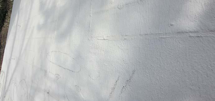
Visual inspection also revealed localized blistering and partial debonding of the surface-applied adhesive zinc anode in limited areas of Pier B (Figure 7). Based on the observed distribution of the defects, moisture ingress and water accumulation behind the zinc sheet are considered the most likely contributing factors. However, these anomalies were confined to relatively small areas, and no evidence of significant deterioration in the overall cathodic
protection performance of the system was observed. Overall, the Baells Bridge case study confirms that surfaceapplied adhesive zinc anodes can provide durable long-term protection under real service conditions and supports the use of laboratory-derived design parameters for infrastructure applications.
Based on the observed distribution of the defects, moisture ingress and water accumulation behind the zinc sheet are considered the most likely contributing factors. However, these anomalies were confined to relatively small areas, and no evidence of significant deterioration in the overall cathodic protection performance of the system was observed.
PIER A PIER B
Figure 6 - Depolarization response measured on Pier A after more than three years of exposure.
Conclusion
Surface-applied adhesive zinc anodes exhibit a clear distance-dependent attenuation of cathodic polarization.
Under the laboratory conditions investigated, the strongest and most consistent polarization was achieved within approximately 20 cm from the anode edge.
Depolarization gradually decreased with time, indicating a transition toward a more stable electrochemical condition.
Long-term monitoring of the Baells Bridge confirmed sustained cathodic protection performance after more than three years of exposure.
Good agreement was observed between laboratory observations and field performance, supporting the use of laboratory evaluations during the design phase.
For infrastructure applications, optimized design should combine throwing power assessment, environmental exposure evaluation, and long-term monitoring in accordance with modern performancebased standards.
Acknowledgment
The authors acknowledge the collaboration between Mapei, Metalnastri and CorMit in the development and monitoring of the cathodic protection system. Special thanks are extended to Mapei Spain, particularly Ms. Carmen Moral, for support during the site visits. ‹
References
[1] Scheffy, C. F. (1981). Bridge deck deterioration: A 1981 perspective. Federal Highway Administration (FHWA), Office of Research.
Figures 7a and 7b - Field observations during the latest monitoring: (top) elevated reservoir water level around Pier B; (bottom) localized blistering and partial debonding observed in limited areas.
[3] AMPP (formerly NACE International). (2023). SP21520-2023: Acceptance criteria for cathodic protection of steel in concrete structures. Houston, TX: AMPP.
[4] ASTM International. (2015). ASTM C876-15: Standard test method for corrosion potentials of uncoated reinforcing steel in concrete. West Conshohocken, PA: ASTM International.
[5] ISO. (2022). ISO 12696:2022 – Cathodic protection of steel in concrete. International Organization for Standardization.
ROAD TO 2050
The European Commission entrusts AIMPLAS with coordinating a pilot Substitution Centre to guide the transition to safer flame‑retardant alternatives
Edited by AIMPLAS Plastic Technology Centre, Paterna - Valencia, Spain
HEFESTOS will support industry and regulators in replacing Brominated Flame Retardants through a trusted, harmonised and science‑based cooperation framework. With regulatory pressure increasing and data often fragmented, the Hub offers organisations early access to structured knowledge, technical dialogue and coordinated substitution efforts.
AIMPLAS, the Plastics Technology Centre, has been selected by the European Commission to lead the new HEFESTOS Hub, a Europeanfunded initiative designed to support the transition away from Brominated Flame Retardants (BFRs) towards safer and more sustainable alternatives. The initiative will focus on key industrial sectors such as construction, automotive, cables, and other strategic applications. Promoted and financed by the European Commission and awarded to AIMPLAS through a competitive tender, HEFESTOS will act as a pilot cooperation framework to explore the feasibility of a future EUlevel Substitution Centre focused on
brominated flame retardants. BFRs have been widely used for decades to meet fire safety requirements in construction, automotive, cables, and other polymer-intensive applications. However, growing evidence of their persistence, toxicity, and potential for bioaccumulation has increased the urgency to accelerate their substitution. Although many companies have already begun exploring alternatives, their efforts to find replacements have failed to gain traction: inconsistent methodologies, limited access to reliable data, and the lack of a secure environment for cross-sector collaboration keep these efforts scattered and without a common direction HEFESTOS aims to address these barriers by developing and testing a harmonised, transparent and science-based framework that enables structured information exchange while fully respecting confidentiality and EU competition law. As coordinator of the initiative, AIMPLAS will act as an independent technical secretariat, facilitating collaboration among industrial stakeholders, research organisations, regulators and other relevant actors. HEFESTOS does not impose obligations or regulatory requirements; instead, it provides a structured and trusted space where organisations can contribute knowledge, share insights and participate in the identification of safer alternatives.
The initiative will generate a consolidated evidence base on BFR uses, alternatives and value chains; identify technical and information gaps; and support the development of a European BFR Substitution Action Roadmap. This roadmap will outline realistic and coordinated pathways for substitution, ensuring that industry perspectives from across the value chain are adequately represented.
Participation in HEFESTOS is open to stakeholders across the value chain, including industry, research organisations, standardisation bodies and regulators. Organisations joining the Hub will do so under a standardised onboarding process that includes a Non-Disclosure Agreement and a Memorandum of Understanding, guaranteeing a secure and competition-compliant environment. Once onboarded, participants will be able to contribute through interviews, questionnaires, technical meetings and discussions on priority applications, and may also engage in pilot actions or voluntary pledges supporting the transition to safer alternatives. In addition, participating organisations will have the opportunity to feature their logo and relevant initiatives on the HEFESTOS website, reinforcing their visibility and commitment to sustainable and safe chemical management.
HEFESTOS represents a significant step towards building a coordinated European approach to hazardous chemical substitution, reinforcing industrial resilience while advancing the objectives of the EU Chemicals Strategy for Sustainability. Through its leadership, AIMPLAS will contribute to shaping a future system that enables consistent, evidence-based and collaborative progress across sectors. ‹
About AIMPLAS
At AIMPLAS, the Plastics Technology Centre, we are committed to building a better world by promoting sustainable innovation in the field of plastics. Our goal is to support companies in creating wealth and employment, while helping to address major societal challenges. We provide comprehensive, tailored solutions that include R&D&I projects, training, competitive and strategic intelligence, technical and legal consultancy, as well as technological services such as analysis and testing. We are firmly committed to sustainability and actively contribute to the 17 United Nations Sustainable Development Goals (SDGs) through both our operations and our social responsibility initiatives. As a member of the Network of Technological Institutes of the Valencian Region (REDIT), we are further empowered to deliver value and foster knowledge transfer within the business community.
Surface treatment solutions for the wind energy industry
Surface treatment solutions for the wind energy industry
Complete turnkey solutions for manufacturers across the wind energy supply chain – from wind towers and offshore foundations to turbine components and automated production lines.
From concept to commissioning – your partner in advanced surface treatment technology.
The paper presents a case study of AC corrosion risk in a complex gas distribution network located in a major European capital, characterized by combined AC/DC interference from railways, metro systems and high-voltage transmission lines. The study highlights the interaction between cathodic overprotection and AC interference, which can trigger autocatalytic corrosion mechanisms. A continuous monitoring approach based on coupon measurements and high-resolution electrochemical data was implemented to assess real operating conditions. The monitoring campaign was developed with the technical contribution of Automa, acting as both technology provider and engineering partner, enabling continuous remote acquisition and analysis of key corrosion parameters. The results demonstrate the importance of integrated monitoring systems for effective integrity management of cathodically protected pipelines.
The risk of AC (alternating current) corrosion has long been associated primarily with the parallel routing of underground pipelines alongside high-voltage alternating current (HVAC) power lines. This risk becomes particularly significant in regions where geographical constraints or urban development lead to the formation of so-called “technological corridors”, areas where multiple utilities, including power lines and pipelines, are forced to share the same path over extended distances.
In recent years, the proliferation of AC-powered railway systems has introduced additional sources of AC interference. At the same time, advances in pipeline coatings (designed to enhance insulation performance) have introduced a new set of challenges. While these modern coatings offer better electrical isolation from the surrounding soil, they also increase the risk of cathodic overprotection when compared to older, more degraded, or less efficient coatings. This combination of increased AC interference and improved pipeline insulation can create conditions favourable for accelerated AC corrosion.
This paper presents a real-world case study observed in a gas distribution network of approximately 120,000 km located in a
major European capital, characterised by high complexity due to the simultaneous presence of multiple sources of electromagnetic interference. These include the metro and railway systems within the urban area, as well as railway lines and high-voltage power lines converging toward the city in the surrounding outskirts. Through this example, the study explores current regulatory criteria and industry standards aimed at managing AC corrosion risk. It also demonstrates how the simultaneous presence of cathodic overprotection and AC interference can trigger an autocatalytic cycle, in which the corrosion process accelerates itself. In such scenarios, continuous monitoring becomes not only beneficial but essential for early detection and timely implementation of corrective measures. The case study highlights practical approaches to AC monitoring and emphasizes the critical role of proactive asset management in preserving pipeline integrity.
The monitoring campaign described in this paper was developed with the technical contribution of Automa, which acted both as technology provider and engineering support partner. The project was initiated after the operator recognized the need for continuous field data in order to better understand the complex interaction between AC interference, DC stray currents and cathodic overprotection.
Figure 1 – AC interference mechanism.
Figure 2 – AC corrosion risk assessment according to ISO 18086.
The absence of long-term datasets made it difficult to evaluate the real behaviour of the system under dynamic operating conditions. Automa supported the project from the early stage by identifying the most relevant monitoring locations and supplying a remote monitoring infrastructure capable of continuous acquisition of electrochemical parameters along the pipeline network. This approach enabled the transition from periodic manual measurements to continuous high-resolution monitoring.
Introduction
There are several mechanisms through which an AC source can interfere with a metal structure (as shown in Figure 1): by inductive coupling, as an effect of the magnetic field generated with respect to an underground structure; by capacitive coupling, in the case of an aerial structure; by conductive coupling in presence of a fault current in the ground, in the case of an underground pipeline. In the case of underground pipelines, under normal operating conditions, the mechanism that can generate AC interference is the first of those shown, the coupling by induction: normally the interference effect is greater as larger the length of the sections where the pipeline and the AC source (high voltage AC lines, railways operated in AC, ...) follow a parallel path.
AC corrosion protection criteria
There are specific international industry standards indicating which electrical parameters shall be monitored, and which are the maximum values allowed for these parameters. The standard ISO 18086:2019 “Corrosion of metals and alloys - Determination of AC corrosion - Protection criteria”1 indicates two steps for the verification of permissible AC interference levels, as shown in Figure 2. It should be noted that the first step only relates to a safety criterion for the maximum permissible touch voltage and does not have a direct rule in the assessment of the AC corrosion risk. The reasons for this value are also explained in detail in the preface to NACE standard SP01772, by considering a hand to hand or hand to foot resistance for an adult male human body of 1500 Ω, so that applying a 15V to that load would yield a current flow of 10 mA.
The criterion, therefore, is based on current density measurements carried out through a coupon whose surface is defined by the standard to be 1 cm2, connected to the structure: under control there is not only the AC current density as obvious to expect, but we are beginning to understand how the level of cathodic protection can also affect the phenomenon of AC corrosion, and therefore the DC current density must also be measured.
1 ISO 18086:2019 “Corrosion of metals and alloys - Determination of AC corrosion - Protection criteria”, (Geneva, Switzerland: ISO – International Organization for Standardization).
2 NACE SP0177-2019 “Mitigation of Alternating Current and Lightning Effects on Metallic Structures and Corrosion Control Systems”, (Houston, TX: NACE).
In the case of underground pipelines, under normal operating conditions, the mechanism that can generate AC interference is the coupling by induction: normally the interference effect is greater as larger the length of the sections where the pipeline and the AC source (high voltage AC lines, railways operated in AC, etc.) follow a parallel path.
Similar values can be found expressed in the NACE standard SP21424-2018 “Alternating Current Corrosion on Cathodically Protected Pipelines: Risk Assessment, Mitigation, and Monitoring”3, where depending on the measured DC current density value, different levels of AC current density are allowed:
If J.dc > 1 A/m2 then J.ac < 30 A/m2; or
if J.dc < 1 A/m2 then J.ac < 100 A/m2
This standard imposes a maximum AC current density limit even if the DC current density is less than 1 A/m2, while the coupon surface of 1 cm2 is indicated as generally used but not mandatory as in the case of the ISO standard. In the standards, the Spread Resistance meaning is described: it is the ohmic resistance through a defect of the coating towards the remote earth and it is the resistance that controls the DC or AC current passing through a defect at a given DC or AC voltage, so in the case of the AC the following applies:
Uac = R’s Iac or Uac = Rs J.ac (1)
where Rs is the normalized Spread Resistance and expressed in Ω·m2
On coating defects (or on the coupon), where the cathodic protection current reaches the surface of the steel, cathodic reactions occur, leading to an increase in pH at the interface and therefore alkalinity.
3
NACE SP21424-2018 “Alternating Current Corrosion on Cathodically Protected Pipelines: Risk Assessment, Mitigation, and Monitoring”, (Houston, TX: NACE).
Since the value of Spread Resistance depends4 both on the size of the defect (decreases as its surface decreases) and on the pH value at the interface (decreases as the pH increases), the DC current density reaching the defect has an effect on it, specifically:
Lower current density leads to a decrease in pH value and thus to an increase of the Spread Resistance
A higher current density leads to an increase in pH value and thus to a decrease of the Spread Resistance
This is where overprotection can have an effect on AC corrosion:
presence of a very electronegative IR-free potential (due to high DC current densities);
decrease in the Spread Resistance value (Uac = Rs * Jac, the more significant the decrease, the more negative the IR-free potential);
possibility of significant AC current density even in the presence of a not particularly high measured AC voltage value.
Regarding the choice about which size of coupon to use, increasing the surface area of the coupon results in a lower average current density since the spread resistance increases linearly with increasing defect diameter and the current density decreases linearly with surface area.
Therefore, the current density is typically underestimated when the surface area of the coupon is chosen to be larger than the maximum defect size on the structure: for this reason, in the case of AC corrosion, the standards indicate the use of a 1 cm2 coupon.
Ac corrosion mechanism in the presence of over-protection
For pipelines with applied cathodic protection, the development of AC corrosion requires simultaneous coexistence of: induced AC, excessive cathodic protection, small coating defects. Under these conditions:
1. Induced alternating current leads to alternating current discharge on coating defects.
2. The density of alternating current is regulated by the alternating voltage and the spread resistance associated with the defect of the coating, through the Ohm’s law.
3. Spread resistance depends on:
the size of the coating defect,
the soil resistivity in the nearby of the coating defect,
the soil chemistry,
the cathodic protection current density in the coating defect.
As shown in Figure 3, the AC current density can lead to the depolarization of the defect: this requires a higher DC current density to maintain a certain cathodic protection potential. Increasing the level of cathodic protection to mitigate AC corrosion, in this case, has the opposite effect: the increase in DC current density further decreases the Spread Resistance at the coating defect due to the production of OH- ions (alkalinization). Through high levels of cathodic protection, the Spread Resistance decreases, thus increasing the density of alternating current, restarting the cycle: this scenario results in an autocatalytic cycle leading to AC corrosion.
4 L.V. Nielsen, M.B. Petersen, L. Bortels, J. Parlongue; “Effect of Coating Defect Size, Coating Defect Geometry, and Cathodic Polarization on Spread Resistance: Consequences in relation to AC Corrosion Monitoring”; Proceedings CEOCOR Congress 2010, (Bruges, Belgium).
Figure 3 - Autocatalytic Nature of AC Corrosion on Cathodically Protected Pipelines described by SP21424.
It therefore becomes clear that, in order to leave this cycle, it is necessary to control both the AC current density and the DC current density.
Analysis of a real field case
The case that will be shown has been detected on a measurement point of the distribution network of a large European city, with the following features:
a very extensive cathodic protection system, which forms a ring around the city centre with outward radiating offshoots that also reach other municipalities,
presence of multiple crossings with DC powered railways and surface metro,
presence of multiple parallels with the HVAC network
Cathodic Protection is guaranteed by two T/Rs.
Regarding the analysed measuring point (MP):
It is located in an area of the CP system that has some km of parallelism with the HVAC line,
The local soil resistivity is around 25 Ω·m.
The MP is equipped with a permanent CSE reference electrode with an integrated 10 cm2 coupon
for this reason, as mentioned before, it should therefore be considered that the measured current density is underestimated compared to the one that would have been measured by using a 1 cm2 coupon,
The MP is equipped with the Automa’s G4C-PRO remote monitoring device capable of performing instant-off measurements on coupon and current density measures.
The measurements shown in Figure 4 correspond to daily reports calculated on measurements performed continuously at a frequency
of 1 Hz (1 measure per second) for each measuring channel. The minimum, average and maximum daily values are shown over a period of 4 days:
Eon.dc: ON potential (DC) expressed in V CSE;
Eon.ac: ON potential (AC) expressed in V;
Eoff: instant-off on coupon, equivalent to IR-Free potential (measured, every second, after a 1 ms wait from switch opening and over a 20 ms interval) expressed in V CSE;
mIon: DC polarisation current of the coupon expressed in mA; as the coupon size is 10 cm2 the shown value corresponds to the current density in A/m2
mIon.ac: AC polarisation current of the coupon expressed in mA; as the coupon size is 10 cm2 the shown value corresponds to the current density in A/m2 (note: the current density value measured on a 1 cm2 coupon would be significantly greater than that measured on the 10 cm2 coupon).
In the absence of coupons, the only available measures would be Eon.dc and Eon.ac, and, on these values, the only possible evaluation would be that relating to the first step of ISO 18086, which would be absolutely respected considering that the highest AC average value along the four days shown (0,424 V) is well below the indicated threshold of 15V. Generally, such a low AC voltage value would never suspect a real risk of AC corrosion, but as can be detected from the DC and AC current densities, we are faced with unacceptable interference levels:
mIon: between 15 A/m2 and 17 A/m2:
greater than the threshold of 1 A/m2 for which (according to ISO 18086) the AC current density value would be indifferent.
mIon.ac: between 35 A/m2 and 39 A/m2:
greater than the threshold of 30 A/m2 indicated by ISO 18086 and NACE SP21424.
Figure 4 - Daily reports of the MP analysed.
The explanation for this situation is given precisely by the significant level of cathodic overprotection present, represented by IR-Free potential values more negative than -1.3 V CSE and very high DC current density values, being the MP in a site suffering cathodic DC interference generated by metro and railway systems. This results in a reduction of the Spread Resistance value, up to the point of generating an AC current density higher than the allowed limits even in the presence of a very low AC voltage. The main evidence of the dependence of this condition on over-protection has been clearly shown when, due to a malfunction, one of the two T/Rs protecting the Cathodic Protection system did shut down, changing the values measured on the Measurement Point as in Figure 5.
On day 21/01 the shutdown of one of the two T/Rs obviously brought a reduction of the DC protection current, with the result that, at a positive shift of the IR-Free potential from -1,3 V CSE to -1,06 V CE, AC current density has become less than half, from average daily values of 28 A/m2 to values of 12 A/m2 possibly again compatible with the acceptance criteria expressed in ISO 18086 and NACE SP21424 (It should be remembered that being the measure made on a 10 cm2 coupon, the result is certainly underestimated compared to the use of a 1 cm2 coupon as required by the aforementioned standards). The trend is also evident in Figure 6, where it is shown the evolution of the daily average values in the two weeks when the switching off of the T/R happened.
In correspondence to the decrease of the cathodic current density (J.dc) there is obviously a simultaneous positive shift of the values of the IR-Free potential measurement (Eoff): this leads to the reduction of the values of the AC current density (J.ac) to permissible values (and a slight increase in the AC voltage values in terms of absolute value, which is almost three times compared to the values measured under overprotection conditions).
The explanation for this situation is given precisely by the significant level of cathodic overprotection present, represented by IR-Free potential values more negative than -1.3 V CSE and very high DC current density values, being the MP in a site suffering cathodic DC interference generated by metro and railway systems. This results in a reduction of the Spread Resistance value, up to the point of generating an AC current density higher than the allowed limits even in the presence of a very low AC voltage.
Figure 5 – Daily reports of the MP analysed.
Unfortunately, from a cathodic protection system management point of view, this presents some critical issues that, from a global perspective, do not allow for an easy management of the problem by simply reducing the current supplied by the T/Rs, since this would lead to problems in reaching protection levels in other areas of the system. For this reason, solutions were evaluated to locally mitigate the AC interference, the installation of which is currently being managed.
It is interesting to note that, even in the long term, this behaviour is confirmed, as shown in Figure 7.
as long as the IR-Free potential remains in protective values, but without overprotection, the AC current density remains within the allowed limits;
as soon as the value of the IR-Free potential returns to over-protection values, the AC current density also exceeds the eligibility limits thus confirming the strong influence that over-protection has on AC corrosion.
Conclusions
As also verified in the real field situation, in the presence of alternating interference, an overprotection condition is able to significantly accelerate the phenomenon of alternating current corrosion: an increased cathodic protection current density increases alkalinity at the defect interface and lowers its Spread Resistance value.
A too low Spread Resistance value, in the presence of alternating interference, may lead to average AC current density values higher than the allowed limit values, even in the presence of AC voltage values much lower than the threshold indicated by the first verification step of ISO 18086 (Vac = Rs * Jac). For this reason, even if it turns out to be the driving force, it is not possible to establish a reliable criterion based only on the value of the AC voltage, since the process is driven by the value of the Spread Resistance and therefore will be dependent on the size of the
Figure 6 – Trend of the daily average values measured on the analysed MP in correspondence with the malfunctioning of the T/R.
Figure 7 – Trend of the daily average values measured on the analysed MP over a period of 19 months.
defect, the type of soil and the local change of alkalinity generated by the DC current density that arrives on the defect/ coupon. The use of coupons is fundamental to monitor both over-protection and DC and AC current densities, and for this reason a remote monitoring device that allows a continuous monitoring of all these electrical parameters simultaneously becomes necessary, especially if it may allow managing two coupons simultaneously: the one with variable size (e.g.: 10 cm2) for the verification of protection and overprotection levels and DC current density, and the 1 cm2 one for the verification of AC current density. ‹
References
1. ISO 18086:2019 “Corrosion of metals and alloys - Determination of AC corrosion - Protection criteria”, (Geneva, Switzerland: ISO – International Organization for Standardization)
2. NACE SP0177-2019 “Mitigation of Alternating Current and Lightning Effects on Metallic Structures and Corrosion Control Systems”, (Houston, TX: NACE).
3. NACE SP21424-2018 “Alternating Current Corrosion on Cathodically Protected Pipelines: Risk Assessment, Mitigation, and Monitoring”, (Houston, TX: NACE).
4. L.V. Nielsen, M.B. Petersen, L. Bortels, J. Parlongue; “Effect of Coating Defect Size, Coating Defect Geometry, and Cathodic Polarization on Spread Resistance: Consequences in relation to AC Corrosion Monitoring”; Proceedings CEOCOR Congress 2010, (Bruges, Belgium).
As also verified in the real field situation, in the presence of alternating interference, an overprotection condition is able
to significantly
accelerate the phenomenon of alternating current corrosion: an increased cathodic protection current density increases alkalinity at
the defect interface and lowers its Spread Resistance value.
The G4C-PRO remote cathodic protection monitoring system by Automa
The monitoring system adopted in the project, which started in 2018 with the first analyses and field assessments carried out on the gas distribution network, is based on the G4C-PRO device, a cathodic protection monitoring unit designed for pipeline integrity applications. Between 2018 and 2019, an initial phase of urgent installations was deployed, focusing on the most critical and interference-prone locations identified by the operator. Following this phase, system expansion was temporarily slowed due to COVID-19 travel restrictions; however, the remote monitoring infrastructure enabled continuous data acquisition and off-site analysis throughout this period. This ensured uninterrupted technical support to the operator for data interpretation and decision-making without the need for on-site interventions. The system is equipped with five galvanically isolated measurement channels, enabling simultaneous acquisition of AC and DC parameters on the same physical input, including ON/OFF potentials, AC interference levels, polarisation currents, drainage and rectifier currents, as well as instant-off coupon measurements. The device installed is powered by battery, allowing installation in complex measurement points such as test posts, rectifiers, and AC/DC drainage systems. Continuous measurements are processed into daily reports based on 86,400 samples per channel, providing statistical indicators such as minimum, maximum, average, standard deviation, and time spent outside predefined thresholds, thus ensuring a comprehensive description of system behaviour over 24-hour cycles.
A key feature of the system is the capability to perform instant-off measurements on coupons with a sampling frequency of up to 1 Hz, enabling accurate evaluation of cathodic overprotection conditions in accordance with ISO 22426 requirements. The platform also supports high-frequency data acquisition across all channels, with configurable transmission modes and remote access functionalities, allowing both periodic reporting and on-demand retrieval of full-resolution datasets.
DONELLI RESTORED THE INTERNAL LINING OF 422 METRES OF PIPELINE AT THE BOLZANO HYDROELECTRIC
POWER STATION, INTEGRATING ROBOTISED SURFACE PREPARATION, CONTROLLED WATER MANAGEMENT, SANDBLASTING, AND THE APPLICATION OF A PROTECTIVE EPOXY COATING.
The small hydroelectric power station in Bolzano (Italy), which began operating in 1901 in the Eggental valley, is a significant example of historic industrial infrastructure that remains fully integrated into the modern energy system. According to figures published by Alperia, the plant produces an average of 17.27 GWh per year, equivalent to the annual consumption of around 5,000 households. The continued operation of a facility of this kind also depends on the ability to plan maintenance aimed at protecting its most heavily stressed metal structures over time. The project carried out by Donelli involved the complete refurbishment of the penstock’s internal lining. Inspections and surveys carried out in previous years had highlighted the natural ageing of the protective system, as well as localised defects, pitting, and discontinuities, making comprehensive intervention necessary. The new coating to be applied had to provide protection under conditions of continuous immersion in fresh water and, at the same time, adapt to an uneven substrate and particularly complex geometries. “The challenge did not lie simply in applying a new coat of paint. Before we could even start the coating process, we had to develop a comprehensive plan to work safely inside the penstock, remove the old coating, manage water and residues in a controlled manner, prepare the steel correctly, and maintain stable environmental conditions throughout the application,” explains Andrea Chini, site manager and on-site project lead for Donelli.
422 metres of pipeline: welded steel and riveted shells
The penstock at the Bolzano plant extends for a total of 422 metres. The main section, reconstructed in 2005, comprises approximately 351.6 metres of DN 1100 pipework made from roll-formed shells, welded longitudinally and joined by circumferential welds.
Downstream, a 62.5-metre-long DN 900 section, dating from 1901, is constructed from shells riveted both longitudinally and circumferentially. The final section, also DN 900 and replaced in 2005, measures approximately 8.45 metres and connects to the power station’s manifold.
The coexistence of a modern welded pipe and an original riveted section required different working methods. On the welded surfaces, surface preparation could proceed more uniformly; in the 1901 segment, however, the rivets, overlapping sheets, irregularities, and pitting necessitated close monitoring and additional manual work. The historic pipe is also partly encased in a concrete casing and accessible only from the inside, making the planning of every phase even more critical.
The worksite was organised into successive sectors to match each section of the penstock with the required work and the relevant inspections. This approach enabled monitoring of the progress of the preparation and coating tasks, control of the operational conditions, and coordination of the movement of personnel and equipment along the pipeline.
The process began with robotic UHP water blasting
The first stage of the project involved removing the old lining using a robotic UHP water blasting process. After verifying that the entire route was accessible and free of obstacles, Donelli installed a dedicated system that could be moved along the pipeline using winches and safety devices. The use of robotic technology enabled controlled operations on such a long, sloping, and uneven surface. Before production began, preliminary tests were carried out on site to adapt the system to the substrate’s actual conditions. The operational set-up was finalised through testing and inspections to ensure uniform removal of the old lining without damaging the metal surface. “In a project of this kind, the key factor is not an individual machine parameter, but the quality of the result achieved on the substrate. Each stage was checked directly in the penstock, ensuring uniform cleaning and proper equipment operation,” adds Chini.
Daily progress varied depending on the section, the condition of the old lining, and the required inspections. Work was therefore scheduled to prioritise quality over speed of execution. The use of robotics reduced operators’ direct exposure to the most strenuous tasks, without eliminating the need for qualified personnel inside the pipeline: on-site checks and external supervision remained essential and were conducted in accordance with specific confinedspace procedures.
The robotic UHP water blasting system advancing inside the penstock. The machine, moved along the pipeline using hauling devices, enabled the controlled removal of the previous coating while reducing operators’ direct exposure.
Internal view of the historic DN 900 section of the penstock, constructed in 1901 from riveted shells.
Recovery and controlled treatment of process water
One of the most significant elements of the UHP phase was the mobile system designed to recover, treat, and reuse process water. This solution significantly reduced overall water consumption and helped keep waste generated by removing the previous lining under control. The water and removed materials were recovered directly from the pipeline and channelled to a dedicated on-site system that performed several separation and treatment stages, organised to prevent spillage and ensure the orderly management of process flows. The equipment also included a filter press, integrated into the process water treatment system.
This suite of equipment enabled efficient residue management and facilitated the on-site reuse of water. Solid residues were stored in suitable containers, awaiting characterisation and disposal in accordance with applicable regulations. This allowed the site to integrate surface preparation with the controlled management of water and removed materials. “The main advantage was the ability to control the entire process. Process water and old paint residues were recovered and managed without any leakage, a crucial requirement in a hydroelectric plant and within a particularly sensitive environmental context,” emphasises Chini.
UHP and sandblasting:
two complementary technologies
Water blasting removed the previous protective system and revealed the substrate’s true condition, but it was not considered a substitute for the subsequent abrasive preparation phase. In fact, following completion of the UHP phase, the surface was sandblasted in accordance with the requirements set out in the project specification, thereby achieving uniform conditions suitable for the application of the new epoxy coating. Sandblasting was carried out using a robotic system on the more regular sections and manually on the geometrically more complex surfaces, particularly around welds, nails, and areas that the machine could not reach
uniformly. The site infrastructure included dedicated systems for dehumidification, dust extraction, abrasive recovery, and compressed air supply.
The spent abrasive was recovered and collected, while ventilation and dust removal units maintained visibility and conditions suitable for subsequent activities. Final cleaning and surface inspections were carried out in accordance with the procedures outlined in the project specifications. Along a pipeline over four hundred metres long, the organisation of auxiliary systems and material handling is integral to the worksite: all necessary services had to keep pace with the progress of the operations without obstructing access or emergency routes, and logistical coordination and material handling kept part of the team occupied on a daily basis.
The riveted section from 1901: preserving the original construction features without erasing them
The most challenging aspect of the project was treating the 62.5-metre original penstock section dating from 1901. Its surface featured longitudinal and circumferential riveting, overlapping sheets, and widespread pitting. Following surface preparation, the entire internal surface of the historic riveted section was completely skim-coated with a suitable epoxy filler. This operation made it possible to fill the widespread pitting and restore a smoother and more uniform substrate before the application of the protective coating system. Particular care was taken around the rivets, joints and overlapping sheets in order to preserve the original construction geometry of the penstock.
This part of the project clearly illustrates the relationship between industrial conservation and maintenance: the goal was not to transform the old pipeline into a new one, but to protect a structure with over a century of service, respecting its design and using materials and inspection methods consistent with current standards.
Applying an epoxy coating with a multi-component system
After preparation, a high-thickness epoxy coating suitable for continuous contact with fresh water was applied. The system comprised a primer, an intermediate coat, and a top coat, each in a different colour to facilitate monitoring of coverage as the work progressed. The application was carried out using a dedicated multi-component system and entrusted to specialist personnel. Throughout this phase, regular checks were carried out to ensure the continuity and uniformity of the coating along the entire length of the pipeline. The thicknesses required by the technical specifications were checked both during application and after polymerisation. The use of different colours for the different coats made it easier to identify any discontinuities, particularly at nail holes, welds, and areas that had previously been repaired. The work proceeded in stages, with intermediate checks and inspections carried out before moving to the next stage. The areas with the most complex geometry were re-examined during the final inspections, after which the systems were dismantled and the equipment packed away. “With a pipeline of this size, there is no room for improvisation. Final quality depends on process stability, team coordination, and the ability to maintain consistent application conditions along its entire length,” explains Chini.
Microclimate, energy continuity, and work in confined spaces
Indeed, lining quality depended primarily on the stability of conditions inside the pipeline. During preparation and application, the microclimate was monitored and kept within the limits specified in the project documentation, with work authorised only when conditions were suitable. Maintaining continuity of site operations was essential to keep the equipment running and to maintain the conditions necessary for paint application. When unscheduled interruptions or changes occurred, the team suspended or reorganised activities, resuming work only after the required
conditions had been restored. In some cases, on the other hand, shifts were extended into the evening to complete stages already underway without compromising quality.
The access points to the penstock, the gradient, and the distance between the forebay and the power plant required specialised logistics planning. Trolleys and winches were used to hoist and lower the equipment; dedicated personnel managed the hauling systems and assisted workers in confined spaces. At one stage of the project, some of the equipment was transported by helicopter from the intermediate platform to the forebay to reduce the time and risks associated with moving it along the route.
Safety was not treated as a separate activity from production. Ventilation, communication, access control, emergency management, rope inspection, and external supervision were essential to carrying out the technical work. The continuous presence of personnel trained to work in confined spaces was critical to all the main phases of installation, UHP treatment, sandblasting, and coating.
Field coordination as a decisive factor
Working on a penstock that could not be fully accessed from a single point, on-site coordination served as the link between planning, safety, inspections, and operational progress. Each day required assessing conditions and adjusting priorities while keeping the project’s planned sequences on track.
Andrea Chini directly supervised on-site teams and activities, liaising with operators, safety personnel, technicians, and the client. His role as site manager and on-site project lead extended beyond production to encompass the overall organisation of the work and prompt responses to requirements that arose at each stage. “The site manager’s task is to ensure that every activity is carried out at the right time and under the appropriate conditions. With such a long pipework, safety, quality, and production must go hand in hand: excellent results are achieved only when the whole team shares the same objective,” emphasises Chini.
Quality control and traceability throughout the pipeline
The control plan covered every phase of the project, from surface preparation controls to intermediate and final coating inspections. The specifications also required supervision by qualified personnel and the conduct of the prescribed tests after paint polymerisation. Daily traceability linked each section to the activities carried out and the relevant checks. In fact, with a long, sloping structure that is not fully visible from a single point, the documentation becomes an operational tool: it allows progress to be tracked and ensures that no area has been excluded from the planned sequences. The records also underscore the continuous changes made to adapt to actual conditions: daily output was assessed not only in terms of linear metres, but also in relation to substrate complexity, inspection times, and environmental conditions. This approach is what makes such a complex project replicable: not the pursuit of maximum speed, but the maintenance of consistent standards throughout the pipeline. The Bolzano project is part of a broader series of complex rehabilitation works carried out by Donelli on hydroelectric penstocks in the region. Between 2023 and 2025, the company also worked on the San Floriano penstock, on the five Cardano penstocks, and at the Lana power station, where the internal manifold was protected and structurally strengthened using a carbon-fibre reinforced lining system. The Bolzano penstock project was subsequently carried out between the end of 2025 and the beginning of 2026.
Maintenance that balances durability, safety, and sustainability
The work site at the Bolzano hydroelectric power station demonstrates that the sustainability of a corrosion protection project depends not on a single product but on the organisation of the entire process. Robotisation, controlled management of water and waste, dust removal, monitoring of environmental conditions, and activity planning have all helped reduce the site’s environmental impact and improve the reliability of the project’s outcome. The project has also bridged two eras of metal construction: the welded shells from 2005 and the riveted section from 1901. Surface treatment technologies have enabled both to be addressed with the same objective: to extend the pipeline’s service life and maintain the efficiency of a plant that continues to produce renewable energy after more than a century. The value of the project also lay in the ability to adapt the work organisation to real-world conditions without compromising safety, quality, or compliance with the power station’s operational requirements. The human aspect of the operation was well summarised by the site manager and on-site project lead, Andrea Chini, in a public post published upon completion of the work: “We are officially out of the tunnel – or, to be precise, the penstock.” A simple phrase that aptly captures both the conclusion of three months’ work carried out amidst snow, freezing temperatures, long shifts, and logistical challenges, and the satisfaction of having completed an extraordinary project. “This work required technology but also, above all, a team capable of adapting on a daily basis. The final result is down to the contribution of everyone who worked inside the penstock and managed safety, material handling, the systems, and the controls. On projects of this kind, no phase can be considered secondary,” Chini concludes. ‹
Detail of the surface of the riveted section after preparation and reinstatement of the protective system. The new coating follows the penstock’s original geometry, leaving the rivets, joints, and overlapping sheets clearly visible.
Robotic surface-preparation equipment used by Donelli during the refurbishment of the Cardano hydroelectric penstocks, carried out between 2024 and 2025. The project involved five penstocks, each approximately 400 metres long and with diameters ranging from 2.5 to 2.8 metres.
The European Corrosion Conference, the EFC’s annual conference, is the flagship event of the international corrosion calendar.
Attracting upwards of a thousand delegates, it is held every year in September in a different European country. EUROCORR is famous for its high technical standard and its popular social programme.
EUROCORR 2026 will explore all aspects of corrosion science, technology and engineering, with a focus on the main theme: ‘Investing in our future: corrosion challenges for green technologies’.
Céad míle fáilte! (A hundred thousand welcomes!). We’re very much looking forward to welcoming you to Dublin in September 2026 for the EUROCORR conference. As a native of the city, I’m delighted and honoured to have the opportunity to showcase everything Dublin has to offer – history, art, theatre, literature, music, dancing, and of course that unique Irish pub culture! You’ll be made to feel relaxed and at home wherever you go.
Practically every aspect of corrosion science and technology will be covered at the conference. We’ll be hosted by the Dublin Convention Centre, a world-class conference venue on the banks of the River Liffey, just a short walk from the geographical centre of the city.
I’m excited to let you know that the conference dinner will be held in the Guinness Storehouse, a seven-floor interactive experience featuring a rooftop bar with a panoramic view of the city and Dublin Bay. Here, you’ll discover over 250 years of brewing history at St. James’s Gate, learn how to pour the perfect pint, have your photo printed in malt on top of a pint of Guinness, and enjoy some traditional Irish music. It promises to be an unforgettable evening!
We hope you’ll also take the time during your visit to explore some of the breathtaking tourist attractions Ireland has to offer. Perched on the western seaboard of Europe and heavily sculpted by glaciers during the last Ice Age, the Emerald Isle boasts some truly spectacular scenery, cloaked in its famous 40 shades of green. I can personally recommend the Cliffs of Moher, Giant’s Causeway, Ring of Kerry, Blarney Castle, Newgrange and Glendalough, and there are many more!
Go n-éirí an bóthar libh (May the road rise to meet you).
Professor Gareth Hinds, EUROCORR 2026 Chair
The Convention Centre Dublin (The CCD) is Ireland’s multi-award-winning, purpose-built international conference and event venue, located in the heart of Dublin.
THE BR EAKDOWN
Coating systems for the railway sector: technical considerations on ISO 9466:2025
Paolo Rami Coating Consultant
ipcm®
Contributor
Drawing on the key provisions of the ISO 9466:2025 standard for coating systems in the railway sector, this article sets out a number of technical considerations and possible developments to improve application effectiveness, integrate process control and management criteria, and define the roles of the professionals involved.
The ISO 9466:2025 standard establishes the performance requirements and acceptance criteria for coating materials used on passenger rolling stock, locomotives, and components. It also provides guidance on coating application processes, product selection, surface preparation, coating application, verification and inspection methods, repairs, refurbishment, and tests to measure the minimum performance of coating products. It applies to all types of liquid and powder coating materials used on railway vehicle bodies, on-board equipment, and constituent parts.
The publication of this standard marked an important step towards establishing a harmonised international benchmark for qualifying coating systems in the railway sector. It aims to standardise criteria for product selection, process qualification, performance verification, and the management of maintenance and repair work, thereby promoting a shared approach among manufacturers, paint producers, maintenance contractors, and railway operators.
In addition to providing a significant framework for the sector, the document offers interesting insights into possible future developments. Some aspects, for example, could be explored in greater depth or incorporated into future revisions to enhance its practical effectiveness and promote greater alignment with established best practices in other areas of the industrial coating industry. Below are a few technical observations on specific aspects of this standard, intended to highlight possible areas for further investigation and development that could contribute to its ongoing refinement and increasingly effective application within the railway sector.
Qualification of the coating system Classification based on the coating’s location within the vehicle
In paragraph 4.2, which covers coating systems, locations, operating environments, and design recommendations, the standard emphasises the need to specify the coating system according to its intended location within the vehicle. However, given that corrosion protection systems are subject to multiple risk factors linked to production processes, substrate characteristics, operating environments, and the chemical and physical stresses to which components are exposed, it may be appropriate to supplement a classification based solely on positioning (external or internal, visible or non-visible) with one based on the part’s risk level. A similar approach has already been adopted in other international standards relating, for example, to welding and bonding processes, in which components are classified according to the consequences of their potential failure.
THE BREAKDOWN
Introducing a classification system that takes into account not only the component’s location but also its criticality in terms of safety and durability would enable more precise definition of the checks to be carried out on the coating process and product, and would help identify the expertise and professional roles that companies should make available depending on the type of component being manufactured.
Qualification tests for the coating system
Clause 4.4.1 provides reference tables for the qualification of coating systems and states that, where individual tests are carried out at a nominal coating thickness different from that specified in the reference table, this must be explicitly stated in the test report. It might be useful to supplement this requirement by introducing specifications for the characteristics of the laboratories responsible for carrying out the chemical and physical tests during both the approval phase of the coating system and the process qualification. In particular, it would be advisable to specify that such tests should be carried out by laboratories with accreditation obtained in accordance with the ISO/IEC 17025 standard and covering the specific tests required by it.
Mechanical characteristics
Clause 4.4.6 contains a reference table for the tests used to determine the mechanical properties of a coating system. The table could be further expanded to include, for selected tests, the corresponding acceptance criteria, which are not specified in the current version of the standard.
Ageing characteristics
In clause 4.4.7, which addresses ageing characteristics, it may be useful to include a reference to filiform corrosion resistance tests in accordance with ISO 4623-1 ‘Paints and varnishes –Determination of resistance to filiform corrosion – Part 1: Steel substrates’ and ISO 4623-2 ‘Paints and varnishes – Determination of resistance to filiform corrosion – Part 2: Aluminium substrates’. These tests enable the assessment of coating systems’ behaviour with respect to a form of corrosion that is particularly critical for painted metal substrates.
The ACET (Accelerated Cyclic Electrochemical Technique) test, as set out in ISO 17463 ‘Paints and varnishes – Guidelines for the determination of anticorrosive properties of organic coatings by accelerated cyclic electrochemical technique’, could also be considered. This method allows the anti-corrosion performance of different coating systems to be compared relatively quickly, providing preliminary indications of their protective effectiveness and thus serving as a valuable tool to support the development and qualification of coating systems.
To supplement the requirements set out in paragraph 4, it may be appropriate to extend the specified tests to include methods for verifying the degree of cross-linking in two-component (2K) coating products, so that the acceptance criteria for subsequent inspections of items in production can be defined at the approval stage. Examples of tests that may be considered include the measurement of film hardness using the pencil test in accordance with ASTM D3363 ‘Standard test method for film hardness by pencil test’, the scratch resistance test in accordance with standard UNI 9395 ‘Paint products – Scratch resistance test (pen method – sclerometer)’, and rub resistance tests using the thinner specified for the paint product or other reference solvents. It may also be useful to include specific references to the requirements for anti-corrosion systems intended to protect axles, wheelsets, and bogies, as per standard EN 13261:2025 ‘Railway applications – Wheel sets and bogies – Axles – Product requirements’. Given the critical importance of these components to the safety of rolling stock, a reference to this standard in Chapter 2, which is dedicated to regulatory references, would provide a more comprehensive overview of the applicable requirements.
Definition and classification of the process stages
Surface cleaning and degreasing
In clause 5.2.3, which addresses surface pre-treatment, the control methods could include additional instruments and tests, such as the use of a Wood’s lamp and a SITA CleanoSpector, or the determination of the presence of soluble contaminants in accordance with ISO 8502-6 ‘Preparation of steel substrates before application of paints and related products – Tests for the assessment of surface cleanliness – Part 6: Extraction of water soluble contaminants for analysis (Bresle method)’.
Surface pre-treatment and preparation methods
In clause 5.2.4, which sets out the specifications for proper surface preparation before coating application, the cleaning grade Sa 2½ should always be associated with the initial rust grade class (A, B, C, or D in accordance with ISO 8501-1), e.g., A Sa 2½, B Sa 2½, C Sa 2½, or D Sa 2½; alternatively, it might be useful to specify that, unless otherwise stated, the reference rust grade is to be considered as A.
The guidelines in the concluding part of clause 5.2.4.3.2 on mechanical pre-treatment and the time interval between the
start of treatment and the application of the first coat are valid. However, it may be advisable to supplement the parameters included (time expressed in hours or days, relative humidity, and ambient temperature) with further requirements regarding environmental conditions, specifying that the application area must be kept ‘free from dust, contamination, and temperature fluctuations’.
In-house testing of standard components
In the section on specifications for in-house testing of massproduced components, Table 13 in clause 6.4.1 could be expanded to include checks at key stages of the corrosion protection process, particularly degreasing and mechanical or chemical surface pre-treatment. For example, before degreasing, it is advisable to carry out preliminary activities such as rounding off sharp edges, removing burrs, and assessing the condition of welded areas in accordance with ISO 8501-3 ‘Preparation of steel substrates before application of paints and related products – Visual assessment of surface cleanliness – Part 3: Preparation grades of welds, edges and other areas with surface imperfections’, with reference to preparation grade P3.
To supplement the requirements set out in paragraph 4, it may be appropriate to extend the specified tests to include methods for verifying the degree of cross-linking in two-component (2K) coating products, so that the acceptance criteria for subsequent inspections of items in production can be defined at the approval stage.
The same considerations expressed for paragraph 5.2.3 apply to the degreasing stage.
As regards mechanical pre-treatment, further checks could be introduced, such as the measurement of surface roughness and the assessment of dust contamination in accordance with ISO 8502-3 ‘Preparation of steel substrates before application of paints and related products – Tests for the assessment of surface cleanliness – Part 3: Assessment of dust on steel surfaces prepared for painting (pressure-sensitive tape method)’. For each test series, it would also be advisable to define minimum acceptability values, in order to ensure objective and uniform assessment criteria throughout the entire production process.
Final considerations
In general, the standard comprehensively addresses the main aspects of coating application on railway vehicles. However, it might be worth adding a dedicated section on process controls in a separate chapter, to be placed before paragraph 6.4, with particular reference to the management of plants and equipment, including measuring instruments; the classification of compressed
air quality in accordance with ISO 8573; the control of abrasives; the control of surface conversion baths; environmental controls, including dew point; and the management of paint product storage. It would also be advisable to supplement the document with a more detailed reference to design measures aimed at preventing corrosion.
A further area for potential development concerns the professional roles involved in industrial processes. At present, the roles and responsibilities of professionals specialising in corrosion protection are not explicitly defined, unlike those in other sectors such as welding and bonding. In this regard, it might be useful to provide clear definitions of professional roles (e.g., coating technicians, quality control inspectors, and applicators), including their training levels, duties, and responsibilities.
Overall, the ISO 9466:2025 standard provides a significant reference framework for the sector. At the same time, it could serve as a starting point for future developments to further strengthen the integration of coating specifications with the management of related industrial processes. ‹
A further area for potential development concerns the professional roles involved in industrial processes. At present, the roles and responsibilities of professionals specialising in corrosion protection are not explicitly defined, unlike those in other sectors such as welding and bonding.
Edited by SciTeeX
How SciTeeX integrates robotic blasting, wire-arc metallizing and robotic painting with airflow management, zeolite concentration and catalytic oxidation.
Automation is reshaping industrial corrosion protection. Robotic blast cleaning and robotic zinc-arc spraying improve the repeatability of surface preparation and metallic coating, while robotic painting delivers consistent film build and higher throughput.
The environmental consequence appears mainly in the organiccoating stage: when solvent-containing materials are applied continuously in large booths, the VOC load can become substantial and sustained. Treating the entire ventilation stream by direct oxidation is often uneconomic because the air volume is high and the VOC concentration is low. SciTeeX therefore applies a process-first strategy: minimize the air that must be discharged, concentrate VOCs on a rotary zeolite wheel, catalytically oxidize the smaller concentrated stream, and recover heat. The following sections describe the general engineering principles behind this approach.
About SciTeeX
SciTeeX is a global engineering and manufacturing company specializing in the design and delivery of advanced surfacetreatment systems. For over 30 years, the company has delivered comprehensive, highly automated solutions to the industry, including robotic and conventional blast cleaning, robotic wire-arc metallizing, automated application of organic coatings, advanced process transport, spray and curing booths, and air-pollutioncontrol systems. With in-house engineering and manufacturing capabilities, SciTeeX delivers complete turnkey projects from concept development and engineering design through manufacturing, installation, commissioning and after-sales service. Its technologies support demanding sectors including energy, transportation, automotive, construction, defence, agriculture and steel-structure production.
Automation changes both production and emissions
SciTeeX’s competence spans the complete protectivecoating sequence. Robotic blast cleaning provides repeatable cleanliness and surface profile; robotic wire-arc spraying applies zinc, aluminium or alloy metallic coatings with controlled gun movement and deposition; and robotic painting applies the organic coating system with repeatable overlap, speed and film build. Workpiece transport, spray booths, curing, ventilation and environmental systems are engineered around the same production logic.
These processes have different emission signatures. Blasting produces abrasive and substrate dust. Arc spraying produces metallic particles and fumes. VOC emissions arise primarily from solvents and other volatile constituents in organic coatings, cleaners and related materials. Automation itself does not create VOCs; however, it enables longer operating hours, stable application rates and higher throughput. The total solvent mass released per hour, and the duration of the release, can therefore become materially greater than in intermittent manual production.
For oversized steel structures, the VOC challenge is compounded by ventilation. A large spray booth may circulate and exhaust very large air quantities to capture overspray, maintain visibility, control the atmosphere and achieve coating quality. If an abatement system is sized simply for the maximum fresh-air flow, filters, ducts, fans, heat exchangers and the oxidizer all become correspondingly large. SciTeeX therefore treats the robotic line, booth modes, air system, VOC mass balance and heat recovery as one integrated process rather than adding an oxidizer at the end.
Why air volume and VOC concentration dominate cost
An oxidizer destroys pollutant mass, but it must transport and heat the carrier air. Capital cost grows with airflow because every flow-dependent component becomes larger. Fan electricity rises with the required volume and pressure, while thermal demand rises with the mass of air that must be brought to the reaction temperature.
The economics become less favourable as VOC concentration falls. Dilute air contains less chemical energy per cubic metre, so oxidation releases less heat relative to the quantity of air being heated. A large, low-concentration stream can therefore require more auxiliary energy per kilogram of VOC destroyed than a smaller, richer stream. High-volume coating booths are consequently a natural application for source reduction and concentration.
From this logic follows a three-part design sequence. First, separate the internal circulation needed for coating quality from the quantity that truly must be discharged. Second, use adsorption to transfer VOCs from the large dilute stream into a much smaller regeneration stream. Third, oxidize that concentrated stream catalytically and recover its heat. Each step improves the energy balance of the next one.
Airflow becomes a controlled process variable
Robotic painting does not eliminate the need for vigorous booth airflow. The spray cloud must still be captured, overspray transported to filters, and temperature and humidity kept stable. The key distinction is between circulation within the booth and exhaust to atmosphere. In automatic operation, with personnel excluded, an engineered proportion of conditioned air may be recirculated when the coating system, solvent balance and safety case permit. Curing commonly uses a still higher recirculation proportion because no spraying takes place.
Any recirculation concept must be designed within the applicable safety framework, including EN 16985 for spray booths using organic coating materials. It requires a defined solvent mass balance, control below the permitted fraction of the lower explosion limit, verified airflow, purge sequences, interlocks between ventilation and application equipment, and controlled
access. Recirculation is therefore a validated operating mode, not merely a damper setting or an energy-saving shortcut. Where several booths share an abatement plant, production planning can reduce simultaneous peak demand. A manually occupied booth at full fresh-air flow can, for example, be paired with another booth in automatic recirculating spray mode, preparation, flash-off or curing, rather than operating all booths at maximum exhaust at the same time. The abatement plant then follows realistic combinations of process modes instead of an unlikely sum of every theoretical maximum.
Variable-speed fans, airflow and pressure measurement, temperature monitoring and automatic compensation for filter loading allow the ventilation system to follow the actual process state. The booth retains the internal air movement required for quality and safety, while the external VOC-treatment load is limited to the necessary volume.
RCCTO: concentrate before destruction
After source airflow has been optimized, the exhaust enters an RCCTO - Rotary Concentrator with Catalytic Oxidizer. Prefiltration section first removes paint particles and dust that could foul the zeolite channels. This protection is essential in coating plants, where gradual particulate contamination would reduce adsorption capacity and increase pressure drop.
The filtered stream passes through a slowly rotating zeolite rotor divided into adsorption, desorption and cooling sectors. In the adsorption sector, hydrophobic zeolite captures VOC molecules while the bulk of the cleaned air passes through. As the rotor turns into the desorption sector, a much smaller heated air stream releases the adsorbed compounds. The cooling sector then restores the rotor to the temperature required for efficient adsorption. Depending on solvent composition and process conditions, the concentrator can reduce the carrier-air volume sent to the oxidizer by an order of magnitude or more, and in suitable applications by several tens to one. The VOC mass is not reduced in the rotor; it is transferred into a smaller, richer stream. This is the central economic function of the zeolite stage: the catalytic oxidizer is sized for the regeneration stream rather than the full booth exhaust.
Hydrophobic zeolites are selected to limit competitive water adsorption, but stable performance still depends on the inlet envelope. Temperature, relative humidity, dust loading, solvent mix and concentration must all be considered. The rotor and catalyst must also be checked for substances that may be poorly adsorbed, corrosive or capable of poisoning the catalyst. Successful RCCTO design begins with a representative coatingmaterial inventory and VOC composition, not only a total-carbon value.
High-volume coating booths are a natural application for source reduction and concentration. Engineering hierarchy: control the process first, minimize the external exhaust second, concentrate the VOC mass third, oxidize the smallest practical stream, and return useful heat to production.
From this logic follows a three-part design sequence.
Catalytic oxidation and the route to autothermal operation
The VOC-rich desorption stream enters a catalytic oxidizer with a preheater, recuperative heat exchanger, heating chamber and catalyst bed. Heat from the cleaned exhaust raises the incoming stream before the burner supplies start-up energy or any remaining deficit. Because the catalyst lowers the required reaction temperature, oxidation can typically take place around 350-450 °C rather than at the substantially higher temperatures used in conventional thermal oxidation. This reduces energy consumption and the tendency to form thermal NOx. On the catalyst, suitable organic compounds are converted mainly to carbon dioxide and water vapour. The reaction is exothermic, so the solvent load becomes a source of process heat. A higher and more stable concentration at the oxidizer inlet improves the possibility of autothermal operation: steady-state operation in which VOC oxidation supplies all of the heat required to maintain the reaction temperature. Autothermal operation should be treated as an engineering target, not an unconditional promise. It depends on solvent calorific value, concentration, flow, ambient conditions, heat losses and catalyst condition. The control system must therefore modulate auxiliary heating continuously. After warm-up, the burner can reduce to zero when the VOC load is sufficient and add only the energy deficit when the load falls.
This approach avoids both overstatement and unnecessary fuel consumption. After internal heat recovery, useful temperature may still remain in the treated gas. A downstream economizer can return this energy to the coating process, for example by preheating booth make-up air, process water or curing circuits. The environmental plant then becomes part of the factory energy system rather than an isolated consumer.
Performance, control and environmental reliability
An RCCTO must remain effective while booth modes, solvent loads and ambient conditions change. Design performance is therefore defined not only by a nominal removal efficiency or outlet concentration, but by the complete operating envelope: minimum and maximum flow, VOC composition and loading, temperature, humidity, particle carry-over, start-up, shutdown and abnormal modes. Emission guarantees must be tied to this documented envelope and verified during commissioning. Typical instrumentation includes flow measurement, differentialpressure monitoring across filters and rotors, temperature sensors, VOC or LEL monitoring where required, variable-speed fan drives, burner and catalyst interlocks, PLC/HMI visualization and data logging. Purge logic, emergency bypass arrangements and safe-state sequences protect both personnel and process availability. Filter condition and catalyst health are operational variables, not maintenance afterthoughts.
The two-stage architecture separates duties that are difficult to perform efficiently in one device. The zeolite rotor handles the large, dilute stream; the catalytic oxidizer handles the small, concentrated stream. This changes the scale and energy balance of the destruction step. The result is not simply a smaller oxidizer, but a controllable system that can follow the production line while keeping environmental performance stable.
The
achievement
is integration, not a single machine
The RCCTO is important, but it is only one element of the engineering solution. Robotic blasting, robotic arc spraying, robotic painting, workpiece transport, booth aerodynamics, filtration, recirculation, solvent mass balance, zeolite adsorption, catalytic oxidation and heat recovery must be designed as interacting subsystems. SciTeeX’s in-house engineering and manufacturing model allows these interfaces to be optimized together, reducing the gaps that often arise when process equipment and emission-control equipment are supplied independently.
For corrosion-protection plants, the broader lesson is that productivity and environmental compliance should be designed at the same time.
DESIGN STAGE GENERAL ENGINEERING PRINCIPLE
Integrated process
Automation raises repeatability and throughput; it also makes emission loads more continuous and predictable. That predictability can be used to optimize airflow, concentration and heat recovery. The most economical cubic metre of air to treat is the one that can be safely retained within the process; the next best is the one whose VOC content can be concentrated before destruction. ‹
Robotic
blasting, robotic arc spraying, robotic painting, workpiece transport, booth aerodynamics, filtration, recirculation, solvent mass balance, zeolite adsorption, catalytic oxidation and heat recovery must be designed as interacting subsystems.
Robot blast cleaning, robotic zinc-arc spraying, robotic painting, curing and workpiece transport designed as one line
Emission mapping Dust and abrasive from blasting; zinc dust and fume from arc spraying; overspray and VOCs from organic coating
VOC mass balance
Booth operating modes
Airflow minimization
Peak-load management
Particle protection
Solvent composition, average and peak release, application rate, flash-off and curing schedule
Manual spray, automatic spray, preparation, flash-off, curing, purge and maintenance
Validated recirculation in automatic and curing modes; discharge only the air required for safety and process control
Coordinate shared booths and process modes rather than adding all theoretical maximum exhausts
Staged filtration protects the zeolite rotor, catalyst and heat exchangers
VOC concentration Rotary zeolite adsorption transfers VOC mass from a large dilute stream to a small rich desorption stream
Catalytic oxidation
Energy objective
Reduced-temperature destruction with internal recuperative heat exchange
Approach autothermal steady state where VOC load permits; recover residual heat for production
Control and safety Flow, pressure, temperature, filter loading, VOC/LEL conditions, purge and interlocks
Materials compatibility Check adsorption, corrosivity and catalyst-poisoning risks for the actual solvent mix
Validation and service Commission across the agreed operating envelope and maintain filters, rotor seals, catalyst and instruments
Note: This table describes a general design methodology. Actual airflow, concentration ratio, catalyst selection and performance guarantees depend on the coating materials, workpiece geometry, production schedule and applicable regulations.
The only international trade fair in Italy, dedicated exclusively to the civil and industrial water sector, returns for its 19th edition in Puglia.
The themes:
• Water treatment and reuse
• Water purification
• Desalination
• Digitalisation
• Leakage reduction
• Sustainability of water resources
• Regulatory and technical updates
THE INDUSTRY MEETING
After the show, the magic: IVS Gala Dinner lights up ChorusLife Arena
After a day filled with business meetings, technical conferences, and bustling exhibition halls, the evening of May 19 marked a complete change of pace at the Industrial Valve Summit. For one night, technology gave way to personal connections—without ever truly disappearing—during the exhibitors-only Gala Dinner, one of the most anticipated events of the exhibition. Held in Bergamo (Italy), IVS brings together the entire international value chain of industrial valves, actuators, and flow control systems serving strategic sectors such as energy, oil and gas, chemicals, and, increasingly, hydrogen and the energy transition.
Stepping into the ChorusLife Arena, guests immediately had the impression of entering another dimension. Dynamic lighting created ever-changing scenography, digital projections transformed the venue into an almost dreamlike setting, and immersive visual effects blended seamlessly with the Arena’s striking architecture.
Even before dinner began, one detail stood out: the sheer scale of the event. The Arena hosted nearly 1,180 guests, bringing together
professionals speaking dozens of different languages yet united by a shared passion for one of the world’s most specialized—and global—industrial sectors. While the conversations during the day revolved around materials, certifications, automation, and emerging applications, the atmosphere that evening became noticeably more relaxed.
The organization behind the event was itself a remarkable performance. The catering, provided by the three-Michelinstarred Da Vittorio restaurant in Brusaporto (Bergamo), succeeded in serving almost 1,200 guests with the precision of a perfectly synchronized production line. The evening’s highlight was the live preparation of the restaurant’s world-famous Paccheri alla Vittorio. Six large cooking stations operated in full view of the guests, serving approximately 600 people, while the rest of the culinary brigade worked behind the scenes to prepare the remaining 600 dishes. The two “production lines”—one visible, the other hidden—operated in flawless synchronization, creating an almost choreographed performance in which every movement was perfectly coordinated and every plate reached
the table at exactly the right temperature. It was a logistical masterpiece that inspired widespread admiration among the attendees.
Meanwhile, a live band performed at the centre of the Arena, providing the soundtrack for the evening and creating the perfect atmosphere for guests to leave their tables and reconnect with colleagues, customers, and friends they had met throughout the exhibition. Perhaps this was the evening’s greatest achievement: transforming an event attended by more than a thousand people into a surprisingly informal environment, where moving naturally from one table to another was effortless and networking continued without the formality typically associated with business appointments.
The evening also featured a celebratory moment. Bernard Controls, sponsor of the Gala Dinner, marked its 90th anniversary on the IVS stage. The milestone carried particular significance at an event dedicated to an industry that continues to evolve rapidly while remaining firmly rooted in the experience, expertise, and reliability of companies that have supported global industrial development for decades.
As dinner gave way to music, after hours spent discussing plants, automation, and technological innovation, the most human side of the exhibition came to the fore.
Perhaps that is the memory exhibitors will take home with them:
not only a flawlessly organized dinner or a spectacular venue, but the feeling of belonging to an international community that shares expertise, embraces common challenges, and - why not? - also enjoys celebrating together the achievements of an industry that continues to look confidently toward the future.
www.industrialvalvesummit.com
EUROCORR 2026 brings the corrosion challenges of a sustainable future to Dublin
Every September, the global corrosion community comes together for EUROCORR, the flagship event of the international corrosion calendar and the annual conference of the European Federation of Corrosion (EFC). Attracting upwards of a thousand delegates from across the globe, it moves each year to a different European city. This year, it comes to Dublin from 6 to 10 September. Organised by the Institute of Materials, Minerals & Mining (IOM3) and the European Federation of Corrosion (EFC), with support from the Institute of Corrosion (ICorr) and DECHEMA, EUROCORR 2026 will explore all aspects of corrosion science, technology and engineering under the theme ‘Investing in our future: corrosion challenges for green technologies’. Over 1,100 delegates and 60 sponsors and exhibitors are registered to attend, which is a testament to the conference’s standing on the global stage and the relevance of its theme to the challenges facing industry today. The technical programme covers every aspect of corrosion science and engineering. Plenary lectures will be delivered by:
Professor Mary Ryan FREng FIMMM
CBE (Imperial College London)
Professor En-Hou Han (Institute of Corrosion Science and Technology, Guangzhou)
Professor Arjan Mol (TU Delft)
Dr Leonardo B Coelho (Ialto)
Professor Damien Féron (Université Paris-Saclay, CEA)
Professor Dawei Zhang (University of Science and Technology Beijing).
“EUROCORR has always placed value on the next generation of specialists, and this year, we’re hosting several social events for professionals at all stages of their career. A Corrosion Summer School focused on green and low-carbon energy technologies
takes place at TU Dublin from 3 to 5 September, immediately before the main conference”, said Professor Gareth Hinds, EUROCORR 2026 Chair.
During the main conference, Young EFC activities run parallel to the programme, including an Early-Career Mingle & YEFC Info Session sponsored by Elsevier and a Career Fair. Young corrosion professionals are also encouraged to participate in the YEFC Best Oral Presentation Awards and YEFC Photo Competition. To encourage gender diversity in the corrosion industry, a Women in Corrosion Luncheon is also being held during the conference, sponsored by Dorken & NOF Metal Coatings. Before the conference kick-off, delegates will be welcomed with a drinks’ reception included in registration. The conference dinner be held at the Guinness Storehouse, a seven-storey building at the heart of St James’s Gate and a landmark in Ireland’s brewing heritage. Guests will not be fully seated, and are encouraged to walk around during the dinner, and can expect a rooftop bar with panoramic views across Dublin and Dublin Bay, over 250 years of brewing history to explore, the
chance to learn how to pour the perfect pint, and of course, traditional Irish music to round off the evening. It promises to be an unforgettable night.
The Convention Centre Dublin is a worldclass facility on the banks of the River Liffey, a short walk from the geographical centre of the city and within easy reach of everything Dublin has to offer. The city is rich in history, literature, art, theatre and music, alongside some of the most welcoming pub culture in Europe.
For those with time to venture further, Ireland’s scenery is spectacular and worth discovering. Shaped by glaciers during the last Ice Age, the Emerald Isle lives up to its name. The Cliffs of Moher, Giant’s Causeway, the Ring of Kerry, Blarney Castle, Newgrange and Glendalough all await to be discovered.
“The conversations we have in Dublin this September will help shape the future of corrosion science and green technology. Be part of them, and we look forward to seeing you. Céad míle fáilte (a hundred thousand welcomes)!”, concludes Hinds.
www.eurocorr2026.org
The most important industry events at your fingertips
myFAIR is a free web app that can be accessed from both desktop and mobile devices, which allows you to stay up-to-date with the leading events of the surface treatment sector.
Registrazione al Tribunale di Monza N° 4 del 26 Marzo 2012 Eos Mktg&Communication srl è iscritta nel Registro degli Operatori di Comunicazione con il numero 19244
POSTE ITALIANE S.P.A. – SPEDIZIONE IN ABBONAMENTO
POSTALE D.L. 353/2003 (CONV. IN L. 27/02/2004 N.46) ART. 1, COMMA 1 LOM/MI/4352
EDITED BY
Eos Mktg&Communication srl
Via Pietro Mascagni, 8 - 20811 Cesano Maderno (MB) - Italy Tel. +39.0362.503215 www.eosmarketing.it - info@eosmarketing.it | www.myipcm.com - info@ipcm.it
EDITORIAL DIRECTOR
Marco Ormellese, Politecnico of Milan
EDITORIAL BOARD
Annalisa Acquesta, University of Naples
Francesco Andreatta, University of Udine
Mehdi Attarchi, Senior Materials & Corrosion Specialist
Andrea Balbo, University of Ferrara
Hadi Beirami, Cathodic Protection Certified Specialist
Rest of world € 250,00 (fast airmail shipping included)
Single copy: € 20,00 EMEA (postage included) - Rest of world (postage excluded)
Back issues: € 40,00 EMEA (postage included) - Rest of world (postage excluded)
Subscriptions can be paid online with PayPal
The meeting place of the global wind industry – onshore & offshore
• 1,600 exhibitors from 40 countries
• First-rate conference programme on six open stages
• Networking with 45,000 international participants
• Recruiting Days on 24 and 25 September
NEW An entire hall dedicated to energy storage windenergyhamburg.com
SAVIM EUROPE DESIGNS AND BUILDS HIGH-VALUE INDUSTRIAL PAINTING SYSTEMS.
Advanced technologies and a highly tailored approach make every project unique - from initial assessment and engineering to post-installation support Built for special applications and complex processes, our plants ensure high performance, consistent quality, and maximum safety, fully compliant with the most rigorous sustainability standards. savimeurope.com