ELECTRIC CHARGES AND FIELDS CHAPTER
1.1
Chapter Outline
1.1 Electric Charges
1.2 Coulomb’s Law
1.3 Forces between Multiple Charges
1.4 Electric Field
1.5 Electric Field Lines
1.6 Continuous Charge Distribution
1.7 Electric Dipole
1.8 Electric Dipole in Uniform External Field
1.9 Electric Flux
1.10 Gauss’s Law and its Applications
1.11 Metal Conductors in Electric Field
Everyone has the experience of seeing a spark or hearing a crackle when synthetic clothes are take off in dry weather. This is almost inevitable with garments like polyester sarees. Another common example of electric discharge is the lightning that every one can see in sky during thunderstorms. Electrostatic deals with the study of forces, fields and potentials arising from static charges . In this chapter, we deal with the basic properties of charges, fields developed due to the point charges and charged bodies which are symmetrical.
The study of phenomenon exhibited by electric charges at rest is called electrostatics.
ELECTRIC CHARGES
Charge is the property of matter that produces and experiences electric and magnetic effects. Point charge: When linear size of charged body is much smaller than the distance under consideration, then the size may be ignored and the charged body is called point charge.
1.1.1 Basic Properties of Charges
Additivity of charges: If a system contains two point charges q1 and q2, the total charge be either positive or negative.
Proper signs have to be used while adding the charges in a system.
Example: If a system contains four isolated charges +1, +2, –3 and +4 in some arbitrary unit, then the total charge of a system = (+1) + (+2) + (–3) + (+4) = +4 in the same unit.
Charge is conserved: Within an isolated system consisting of many charged bodies, charges may get redistributed due to interactions among the bodies. It is found that the total charge of the isolated system is always conserved. When we rub two bodies, what one body gains in charge, the other body loses.
It is not possible to create or destroy net charge carried by any isolated system, although the charge carrying particles may be created or destroyed in a process. Sometimes nature creates charged particles. A neutron turns into a proton and an electron. The proton and electron thus created have equal and opposite charges and the total charge is zero, before and after the creation.
1: Electric Charges and Fields
Charge is quantised: Every existing charge is an integral multiple of a basic unit of charge (electron) and charge is always transferred as an integral multiple of charge of an electron i.e. Q = ± n e. Here, n is an integer and e is electron charge e = 1.6×10 –19 C.
In the International System (SI) of units, a unit of charge is called a coulomb and is denoted by the symbol C.
The quantisation of electric charge was experimentally verified by R.A. Millikan in oil drop experiment.
If a body is to be charged positively by 1 C, then 6.25 × 10¹⁸ electrons must be removed from it.
1 1 1610 62510 19 C18electrons . .
Charge is relativistically invariant: Charge does not undergo any change due to its motion.
Any excess charge given to a conductor, always resides on the outer surface of the conductor.
The surface charge density tends to be very large at sharp points of an isolated conductor.
This is why charge leaks from sharp points. This principle is called ‘Action of points’.
Lightning rods used on tall buildings to prevent lightning from striking the building work on this principle. Lighting rods either neutralist or conducts the charge of the cloud to the ground
1. If 109 electrons move out of a body to another body every second, how much time is required to get a total charge of 1 C on the other body?
Sol. In one second, 109 electrons move out of the body. The charge given out in one second is 1.6 × 10–19 × 109 C
= 1.6 × 10⁻¹⁰ C.
The time required to accumulate a charge of 1 C can be estimated to t = 1 C ÷ (1.6 × 10⁻¹⁰ C/s) = 6.25 × 10⁹ s = 6.25 × 10⁹ ÷ (365 × 24 × 3600) years
= 198 years.
One coulomb is a very large unit for many practical purposes.
Try yourself:
1. How much positive and negative charge is there in a cup of water? Assume that mass of one cup of water is 250 g.
Ans: 1.34 ×10⁷ C
1.1.2 Electrification
The process of giving charge to a body is called electrification.
Every substance is made of atoms. An atom consists of positively charged nucleus at the centre and around it negatively charged electrons revolve in different orbits. Here, the amount of total positive charge is equal to the amount of total negative charge in an atom.
So, atom in a whole is electrically neutral. If a body loses some of the electrons, the deficiency creates excess of positive charge on it and the body is said to be positively charged. Similarly, if a body acquires some additional number of electrons, the body becomes negatively charged.
1.1.3 Methods of Electrification
i) Charging by friction:
When two glass rods rubbed with wool or silk cloth are brought close to each other, they repel each other. The two strands of wool or two pieces of silk cloth, with which the rods were rubbed, also repel each other. However, the glass rod and wool attracted each other.
Similarly two plastic rods rubbed with cat’s fur repelled each other but attracted the fur. On the other hand, the plastic rod attracts the glass rod and repel the silk or wool with
which the glass rod is rubbed. The glass rod repels the fur. In this process when two bodies are rubbed together, electrons are transferred from one body to the other.
The substance with higher electron affinity gains electrons and hence it becomes negatively charged. The one with lesser electron affinity losses electrons and becomes positively charged. In this method, bodies acquire equal and unlike charges
Example: When a glass rod is rubbed with silk, the glass rod becomes positively charged while the silk negatively charged.
ii) Charging by conduction:
If a charged body is kept in contact with an uncharged body, then the uncharged body becomes charged due to transfer of electrons. If the charged body is positive, then it will withdraw some electrons from the uncharged body. If the charged body is negative, then it will transfer some of its excess electrons to the uncharged body.
After conduction, both bodies acquire the charge of same nature. So they repel each other. Thus, conduction precedes repulsion.
If two identical metal spheres carrying charges q 1 and q 2 are brought in contact, then the total charge is equally shared due to conduction.
Example: A metal sphere can be charged by induction as shown in below figure. When a positively charged rod is brought near a neutral metal sphere which is on insulating stand as shown in fig (a), the positively charged rod attracts the negative charges in the sphere towards the rod and repels the positive charges away.
Now, the sphere is connected to the ground through a metal wire as shown in fig (b). (The earth can be treated as a good conductor and a huge reservoir of charge). Then, electrons will flow from the ground to neutralize the positive charge on the metal sphere as shown in fig (c).
iii) Charging by Induction:
When a charged body is kept closer to a neutral body, charge is induced in the neutral body. This induction is due to realignment of charge in the neutral body. The nearer side of neutral body gets unlike charge and the farther end gets like charge, hence induction precedes attraction.
Inducing body neither gains nor loses the charge.
Now, the metal wire is removed and the positively charged rod is taken away. Then, we are left with a uniformly distributed negative charge on the sphere as shown in fig(d).
Key Insights:
■ If a dielectric is charged by induction then induced charge q’ is less than inducing charge q.
■ The nature of induced charge is always opposite to that of inducing charge.
■ Charging a body by means of induction is preferable since the same charged body can be used to charge any number of bodies without loss of charge.
1.1.4 Gold Leaf Electroscope
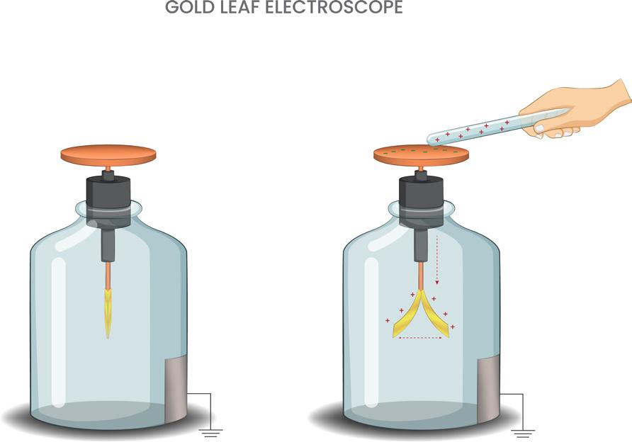
A simple apparatus to detect charge on a body is the gold-leafelectroscope [fig. (a)]. It consists of a vertical metal rod housed in a box, with two thin gold leaves attached to its bottom end. When a charged object touches the metal knob at the top of the rod, charge flows on to the leaves and they diverge. The degree of divergence is an indicator of the amount of charge.
curtain [ fig. (b)]. The rod is fitted through the hole of cork which is at the neck of a bottle. The ball end of rod is projecting about 5 cm above the cork and the flat end is on lower side of bottle. The rod can be slide through the hole in the cork. A small thin folded aluminium foil (about 6 cm in length) is attached to the flattened end of the rod by cellulose tape. This forms the leaves of the electroscope. A paper scale may be put inside the bottle in advance to measure the separation of leaves. The separation is a rough measure of the amount of charge on the electroscope.
On charging the curtain rod by touching the ball end with an electrified body, charge is transferred to the attached aluminium foil through the curtain rod. Both the leaves of the foil get similar charge and repel each other. The divergence in the leaves depends on the amount of charge on them.
A simple electroscope consists of a thin aluminium curtain rod of length about 20 cm with one ball end fitted for hanging the
Key Insights:
■ Repulsion is the sure test to detect charge on a body (or) repulsion is the sure test of electrification.
If a positively charged body is brought near a negatively charged body or uncharged body, there exists a force of attraction. So, the attraction may be due to oppositely charged body or uncharged body. If a positively charged body is brought near positively charged body there exists a force of repulsion. Thus, repulsion is the sure test of electrification.
1.1.5 Conductors and Insulators
A metal rod held in hand and rubbed with wool will not show any sign of being charged. However, if a metal rod with a wooden or plastic handle is rubbed without touching its metal part, it shows signs of charging. Suppose we connect one end of a copper wire to a neutral pith ball and the other end to a negatively charged plastic rod. We will find
that the pith ball acquires a negative charge. If a similar experiment is repeated with a nylon thread or a rubber band, no transfer of charge will take place from the plastic rod to the pith ball.
Conductor: Some substances readily allow passage of electricity through them, others do not. Those which allow electricity to pass through them easily are called conductors. They have electric charges (electrons) that are comparatively free to move inside the material. Metals, human bodies, animal bodies and earth are conductors.
Insulators : Most of the non-metals like glass, porcelain, plastic, nylon, wood offer high resistance to the passage of electricity through them. They are called insulators.
When some charge is transferred to a conductor, it readily gets distributed over the entire surface of the conductor. If some charge is put on an insulator, it stays at the same place.
TEST YOURSELF
1. A and B are two identical spheres having charge on them 7 μC and 1 μC, respectively. Now, both spheres are connected by a wire. Calculate the flow of charge from A to B.
(1) 8 μC (2) 4 μC
(3) 3 μC (4) 1.5 μC
2. If a charge on the body is –1 nC, then how many excess electrons are present on the body?
(1) 1.6 × 10¹⁹ (2) 6.25 × 10⁹
(3) 6.25 × 1027 (4) 6.25 × 1028
3. How many electrons must be removed from a piece of metal to give it a positive charge of 1.0 × 10⁻⁷ C?
(1) 6.25 × 10¹¹ (2) 62.5 × 10¹¹
(3) 62.5 × 10⁻¹¹ (4) 625 × 1011
Answer Key
(1) 3 (2) 2 (3) 1
1.2 COULOMB’S LAW
Electric force between charged objects were measured quantitatively by Charles Coulomb. The force of attraction or repulsion between charges exists even in vacuum. Coulomb's law states that the force of attraction or repulsion between two stationary electric charges is directly proportional to the product of magnitude of the two charges and is inversely proportional to the square of the distance between them and this force acts along the line joining those two charges.
B q2 r q1
Consider two point charges q 1and q 2 at rest at points A and B . The separation between those two charges is r. As per the statement, the force F acting between the two charges is proportional to q1q2 and inversely proportional to r2 .
r FKqq r 12 20 12 2 or
Here, K 0 is proportionality constant. The value of K o depends on the medium between the charges and also on the system of units in which the charges and distance r are expressed. K 0 is known as coulomb’s constant. In SI system, for free space, i.e., air or vacuum, K 0 0 1 4


where is called the permittivity of free space, with = 8.8542 × 10⁻¹² C2/Nm2
In free space, we can write, Fqq r 0 0 12 2 1 4
This is the mathematical form of Coulomb’s inverse square law in free space.
In SI system, the charges are expressed in coulomb and distance in metre. The value
of K 0 is 9 × 10⁹ Nm2/C2 in that system. Now, Coulomb’s law can be written as
Fqq r 0 912 2 910() innewton
when, q1 = q2 = 1 C and r = 1 m then, F = 9 × 10⁹ N
Definition of coulomb: Coulomb is that amount of charge when placed at a distance of one meter from an identical charge in air or vacuum, experiences a repulsive force of 9×10⁹N.
Coulomb is a big unit. 1 coulomb of charge is equvalent to 6.25 × 10¹⁸ electrons.
1.2.1 Limitations of Coulomb’s Law
i) Coulomb’s law is valid for point charges only. Suppose if two large conducting spheres having charges q 1 and q 2 are separated by certain distance, the actual force between those will be different from the value obtained from the formula, because of electrostatic induction.
ii) Coulomb’s law is valid only for static charges. Suppose if two charges are moving, then both will have an associated magnetic field also, in addition to electrostatic field. So the net force will be vector sum of electrostatic force and the magnetic force.
em
If one of the charges is at rest, then F m = 0 and now coulomb’s law can be applied.
2. Two charges 2 µ C and 1 µ C are placed at a distance of 10 cm. Where should a third charge be placed between them so that it does not experience any force.
Sol. Q1 = 2 µ C = 2 × 10⁻⁶ C
Q2 = 1 µ C = 1 × 10⁻⁶ C
d = 10 cm
Let the third charge Q be placed at a distance of x from Q1 then x = ?
The resultant force on 3rd charge is zero.
R 120
By square rooting on both sides and solving further, we get, x = 5.9 cm from 2 µ C
Shortcut:
(from 1 µ C) [ + for like charges, - for unlike charges]
Try yourself:
2. Two equal point charges are kept at a separation and magnitude of electric force acting between then is F. If 50% of one point charge is transferred to the other charge, then find the new magnitude of electric force acting between them.
Ans: 3 4 F
1.2.2 Coulomb’s Law in Vector Form
Suppose r1 and r 2 be the position vectors of point charges q1 and q2 respectively. Let force on q1 due to q2 is F12 and force on q2 due to q1 is F21
Coulomb’s force between q1and q2 located at r1 and r 2 is expressed as
Key Insights:
■ Electrostatic force is a central force.
■ This law is analogous to Newton’s law of gravitation in mechanics.
■ Electrostatic force is a conservative force.
■ Coulomb's force always forms actionreaction pair.
■ Gravitational force is always attractive where as Coulomb's force is either attractive or repulsive.
From the above equations, we can observe that FF1221 , which explains that coulomb’s law agrees with Newton’s third law.
The above equation is valid for any sign of q1 and q2 wheth er positive or negative. If q 1 and q 2 are of the same sign, F21 is along r21 which denotes repulsion. If q1 and q2 are of opposite signs, F21 is along – r21 which denotes attraction.
3. 1 µC point charge is at the origin, another point charge 2 µC is placed at point (3 m, 4 m). Find the vector expression for the force experienced by 2 µC charge.
Sol. Fij ij 910 1210 5 34 34 1441034 9 12 222 6 N N
Try yourself:
3. Two point charges 3 μC and 4 μC are placed at points A(2 m, 0) and B (0, 2 m) respectively. A third point charge –1 μC is placed at the origin. Find the vector expression for the force experienced by the –1 μC charge. Ans: 2251403 3 . ij
■ Gravitational force between two bodies does not depend upon medium present between them but Coulomb’s force between two charges depends on the medium between them.
■ The force between two charges is not affected by the presence of any charge in its vicinity.
1.2.3 Permittivity of Medium
The medium surrounding charged bodies affect the electric force. This is verified experimentally. It is observed that the force between two point charges is maximum in free space. A medium always reduces this force.
The property of the medium which influences the force between the charges is known as the permittivity and is denoted by ∈
Permittivity of a medium explains about its response when charges are kept in it.
In SI system, for medium other than free space, the constant K 1 4 so, that we can write the equation for the force between the charges as, Fqq r F Fr 1 4 12 2 0 0
∈ r is known as the relative permittivity of the medium. It is a constant for a given medium and it gives the extent to which the force between two charges separated by a medium decreases compared with the force between the same charges in free space separated by the same distance.
1.2.4 Relative Permittivity
Relative permittivity of a medium is defined as the ratio of permittivity of the medium to permittivity of free space (or) air.
Relative permittivity of a medium is defined as the ratio of electrostatic force (F0) between two charges in air to the force ( F ) between the same two charges kept in the medium at same separation.
Dielectric constant (or) Relative permittivity,
K = permittivityofthemedium permittivityoffreespace
It has no units and no dimensions


Relative permittivity is also known as dielectric constant K of the medium or specific inductive capacity.
Hence, the mathematical form of inverse square law is given as
Key Insights:
■ When the same charges are separated by the same distance in two different media, F K qq r 1 10 12 2 11 4 .....(1) and, F K qq r 2 20 12 2 11 4 .....(2) from (1) and (2), F1K1 = F2K2
■ When the same charges are separated by different distances in the same medium, then
Fd2= constant ( or ) F1d1 2 = F2d2 2
■ If different charges are at the same separation in a given medium F F qq qq ’’’ = 12 12
■ If the force between two charges in two differ ent media is the same for different separations, then F K qq r 11 40 122constant
Kr2 = constant (or) K1r1 2 = K2r2 2
For free space or vacuum or air, K = 1 and for a good conductor like metals, K = ∞
Conclusion
■ The introduction of a glass slab between two charges will decrease the magnitude of force between them.
■ The introduction of a metallic slab between two charges will decrease the magnitude of force to zero.
■ If the force between two charges separated by a distance r0 in vacuum or air is same as the force between the same charges separated by a distance r in a medium, then the effective distance r in medium for a distance r0 in vacuum is calculated as,
Krrr r K 2 0 20
Here, K is dielectric constant of the medium.
Similarly, the effective distance in vacuum for a dielectric slab of thickness x and dielectric constant K is xxK eff = .
■ If a large diel ectric slab of dielectric constant K and thickness x is placed in between two charges, then the net distance between the charges is rrxxK .
Two point sized identical spheres carrying charges q1 and q2 on them are separated by certain distance. The mutual force between them is F. Those two are brought in contact and kept at the same separation, then final charges on them, qq qq ’’ 12 12 2
Now, the force between them is F’
■ If charge q is spread over a region instead of being concentrated at particular p oint, the force applied by it on point charge Q is
4. A uniformly charged rod AB of length l has a linear charge density λ C/m. A point charge +Q is placed at point C as shown is figure. Find the magnitude of electric force acting on the point charge.
Charge on the element of length dx is dQ = λdx Force acting on Q due to dQ is
x x Qdx x
Try yourself:
4. A ring of radius R is with a uniformly distributed charge Q on it. A charge q is now placed at the centre of the ring. Find the increment in tension in the ring. Ans: T Qq R 2028
TEST YOURSELF
1. Two identical copper spheres are separated by 1m in vacuum. How many electrons would have to be removed from one sphere and added to the other so that they now attract each other with a force of 0.9 N?
(1) 6.25 × 10¹⁵
(2) 62.5 × 10¹⁵
(3) 6.25 × 10¹³
(4) 0.65 × 10¹³
2. Two electrons separated by distance r experience a force F between them. The force between a proton and a singly ionised helium atom separated by distance 2 r is (1) 4F (2) 2F (3) F/2 (4) F/4
3. N fundamental charges, each of charge ‘ q’, are to be distributed as two point charges separated by a fixed distance. Then, the maximum to minimum force be ars a ratio of (N is even and greater than 2 )
(1) 2 2 (1) 4 N N (2) () 42 1 N N (3) () 2 41 N N (4) () 22 1 N N
4. Two point charges +2 C and +6 C repel each other with a force of 12 N. If a charge q is given to each of these charges, then they attract with 4 N. Then, the value of q is (1) +4 C (2) –2 C (3) –4 C (4) +2 C
5. Two small balls, each having equal positive charge Q coulomb , are suspended by two insulating strings of equal length L metres, from a hook fixed to a stand. The whole setup is taken into space where there is no gravity (state of weightlessness). Then, the angle θ between the two strings is (1) 0° (2) 90° (3) 180° (4) 0° < θ < 180°
6. Two point charges A and B, having charges + Q and –Q, respectively, are placed a certain distance apart, and the force acting between them is F. If 25% charge of A is transferred to B , then the force between the charges becomes (1) 16 9 F (2) 4 3 F (3) F (4) 9 16 F
7. Three equal charges q1, q2, and q3 are placed at the three corners ABC of a square ABCD If the force between the charges at A and B (on q1 and q2) is F12 and that between A and C is F13, then the ratio of magnitudes F12 and F 13 is
(1) 1 2 (2) 2 (3) 1 2 (4) 2
Answer Key
(1) 3 (2) 4 (3) 3 (4) 3 (5) 3 (6) 4 (7) 2
1.3 FORCES BETWEEN MULTIPLE CHARGES
The resultant force on any point charge due to a number of other charges is the vector sum of all the forces on that charge due to the other charges taken one at a time. The individual forces are unaffected due to the presence of other charges. This is known as principle of superposition.
Consider a system of stationary point charges q1, q2 ,..........., qn in vacuum. There is also a stationary point charge q such that its distance from q1 is r1, its distance from q2 is r2 ............ its distance from qn is r n .
The force acting on q due to q1 is Fqq r r 1 0 1 1 21 1 4
The force acting on q due to q2 is Fqq r r 2 0 2 2 22 1 4
Similarly, the force acting on q due to qn is Fqq r nr n n n 1 402
The net force acting on q is given by FFFFFF nn 123
FFF n 12,, ......... are to be added vectorially. For negative charges the direction also gets reversed for the forces.
5. Three chargers +q, –q and +q are kept at the corners of an equilateral triangle of side d. Find the resultant electric force on a charge +q placed at the centroid O of the triangle.
Sol. Let the force acting on +q charge at O due to +q at A be F1, +q at B be F2 and –q at C be F 3 Here, AO = OB = OC = d 3
and neutral.
A charge is said to be in stable equilibrium, if it has a tendency of returning to its position when disturbed. Potential energy of the particle will be minimum in the stable equilibrium.
A charge is said to be in unstable equilibrium if it will not have a tendency of returning to initial position when disturbed. Potential energy of the particle will be maximum in the unstable equilibrium.
A charge is said to be in neutral equilibrium, if it has a tendency of remaining at rest in new position also even if it is disturbed from its original position.
Charged particle can be in stable equilibrium for displacem ent along one specific direction and in unstable equilibrium along other directions.
6. Three charges q each are at vertices of equilateral triangle of side r . How much charge should be placed at the centroid so that the system remains in equilibrium?
(as angle between F1 and F2 is 1200)
Direction of F 4 is along the direction of F3. Hence the resultant force on +q at O is
Try yourself:
5. Four charges of +q, +q, +q and +q are placed at the corners A, B, C and D of a square of side a. Find the resultant force on the charge at D.
1.3.1 Equilibrium of System of Charges
For any object of the system, if net force acting on it is zero and net torque on it is zero, then we can say that it is in equilibrium. For a system of point charges, net force F = 0 for translational equilibrium. There are three types of equilibrium namely stable, unstable
Sol. q
Due to three identical charges kept at three corners of a triangle, null point ( E = 0) is formed at centre O. Let Q be the charge placed at centre of triangle then the charge Q is in equilibrium.
For system to be in equilibrium the force on each charge must be zero.
Consider the forces on charge at C. Let FA, FB and F 0 be the forces on the charge at C due to the charges at A, B and O respectively.
FF q a AB 1 40 2 2
Angle between FA and FB is 60 The magnitude of resultant of
The direction of resultant is along OC
The force on C due to Q is
The resultant force on charge at C is Zero.
Negative sign indicates that the force FO is opposite to the resultant of FA and FB
7. A Point Charge +Q is placed at the origin. Two other point charges + q and +q are fixed at points A(+l, 0) and B(–l, 0). Discuss the type of equilibrium of the system of charges along x- and y-axes.
is slightly moved from the origin along x-axis and released, then due to the repulsive force exerted by the charges at A and B, the charge +Q will start moving towards its equilibrium position O, So the equilibrium of the system is stable along x-axis.
Try yourself:
6. Four identical charges each Q are placed at four corners of a square of side a. Find the charge to be placed at the centre of the square so that the system of charges is in equilibrium.
Ans: (221) 4 Q +
Key Insights:
■ A shell of uniform charge attracts or repels a charged particle that is outside the shell as if all the charge on that conducting shell were concentrated at its centre. q1 q1 q2 q2 r r + + + + + +
■ A uniformly charged shell exerts no electrostatic force on a charged particle located inside the shell q1 q2 + + + + + + + +
Here force between q1 and q2 = 0
TEST YOURSELF
1. Two charges 2 μC and 1 μC are placed at a distance of 10 cm. The position of third charge from 2 μC between them, so that it does not experience any force, is (1) 7 cm (2) 2 cm (3) 5.858 cm (4) 8 cm
If the charge + Q is slightly displaced along y-axis and released then due to the repulsive forces exerted by the charges at A and B, the charge + Q will continue to move away from the origin along y-axis, So the equilibrium is unstable along y-axis. On the contrary, if + Q
2. Three point charges Q1, Q2, and Q3, in that order, are placed equally spaced along a straight line. Q 2 and Q 3 are equal in magnitude but opposite in sign. If the net force on Q3 is zero, the value of Q1 is
(1) Q1 = |Q3| (2) 13 2 QQ =
(3) Q1 = 2|Q3| (4) Q1 = 4|Q2|
3. Four charges are arranged at the corners of a square ABCD, as shown in the figure below. The force on the charge kept at the centre is
charge creates an electric field in the space around it. A second charged particle does not interact directly with the first; rather, it responds to whatever field it encounters. In the sense, the field acts as a mediator between the particles.
Electric field: T he space around an electric charge where its influence can be felt by another charge is called electric field. In general, electric field is said to exist in a region in which an electric charge experiences electrostatic force.
1.4.1 Intensity of Electric Field
(1) zero
(2) along the diagonal AC (3) along the diagonal BD (4) perpendicular to side AB
4. For the given figure, find the ratio 12 13 forceondueto forceondueto qq qq
300 q2=3Q (1) 7 2 (2) 3 2 (3) 33 2 (4) 9 2 Answer Key (1) 3 (2) 4 (3) 3 (4) 4
1.4 ELECTRIC FIELD
Consider two point charges separated by some distance. We know that the particles interact, but exactly how does one particle sense the presence of the other? We say that an electric
“The intensity of electric field or electric field strength at a point in space is defined as the force experienced by unit positive test charge placed at that point”.
The intensity of electric field is often called as electric field strength.
Consider an electric field in a given region. Bring a charge q0 to a given point in that field without disturbing any other charge th at has produced the field.
Let F be the electric force experienced by q0 and it is found to be proportional to q0
Fq FEq 00
Here, E is proportionality constant called electric field strength E F q = 0
Electric field strength is a vector quantity. Its direction is the direction along which a free positive charge experiences the force in the electric field.
The SI unit of electric field strength is newton per coulomb (NC–1). It can also be expressed in volt per metre (Vm –1).
Electric field can be uniform or non uniform.
A uniform electric field is that in which at every point, the intensity of the electric field is the same both in magnitude and direction.
Example: Electric field between the plates of parallel plate condenser
A non-uniform electric field is that in which the intensity of electric field changes from point to point either in magnitude or in direction or in both.
Example: Electric field due to a point charge
1.4.2 Electric Field Intensity due to an Isolated Point Charge
Consider a point charge Q placed at point A as shown. Let us find the electric field E at a point P at a distance r from charge Q. Imagine a positive test charge q 0 at P . The charge Q produces a field E at P. Q A P r q0
The force applied by Q on q0 is given by F Qq r 1 40 0 2 . This acts along AP.
According to definition, E F q E Q r r q lim 00002 1 4
If q0 is positive, E is along AP and if q0 is negative E will be along PA .
If the charge Q is in a medium of permittivity ε, and dielectric constant K where, K 0 , the intensity of electric field in a medium (Emed) is given by E Q r med 1 42 E E K med free space
8. A positive charge q is placed in front of a conducting solid cube at a distance d from
its centre. Find the electric field at the centre of the cube due to the charges appearing on its surface.[Hint: The net electric field at the centre of the cube due to all the charges must be zero.]
Sol. Charges will induce on the surface of the cube due to the charge q. Let E1 be the electric field due to the charges appearing on the surface of the cube. If E2 is the electric field due to charge q, then += 120EE (or) =− 12EE (or) = 12EE
The electric field due to charge q at the centre of the cube,
Try yourself:
7. Magnitude of electric field at a point produced by a point charge is E . If the magnitude of the point charge is doubled and the distance of the point from the charge is halved then find the magnitude of new electric field
Ans: 8E
Key Insights:
■ If q is positive charge, then E is along A to P i.e., away from the charge.
■ If q is negative charge, E is along t to A i.e., towards the charge.
■ Electric field due to many charges can be obtained by the principle of superposition i.e., If EE E n 12,..... be the electric fields produced by q1, q2, .... qn at a point, then the resultant field at that point is
9. An infinite number of charges each q are placed in the x -axis at distances of 1, 2, 4, 8,....... (in m) from the origin. If the charges are alternately positive and negative, find the intensity of electric field at origin.
Sol. The electric field intensities due to positive charges at origin is away from the charges and due to –ve charges the field intensity is towards the charges
■ q is kept at that point such that force acting on that charge is F , we can write Fq E =
Here, if q is positive, then FE || ; if q is negative, then FE || -
10. Calculate the electric field intensity which would be just sufficient to balance the weight of an electron. If this electric field is produced by a second electron located below the first one, what would be the distance between them?
[Given: e = 1.6 × 10⁻¹⁹ C, m = 9.1 × 10⁻³¹ kg and g = 9.8 m/s2]
Sol. Force on a charge e in an electric field E F e = eE
So, according to given problem, F e = W i.e., eE = mg
As this intensity E is produced by another electron B, located at a distance r below A
The resultant intensity at the origin
Since the expression in the bracket is in GP with
Try yourself:
8. Two point charges Q/ 2 and Q are placed at points A(a, 0) and B(0, 2a) respectively. What is the magnitude of electric field at the origin?
Ans: 2 5 4 kQ a
Try yourself:
9. A point charge q is placed at origin. E A , E B and EC be the electric field at three points A(1, 2, 3), B(1, 1, -1) and C(2, 2, 2) due to charge q. Give the possible relations between the above field strengths.
Ans: EEEE BCAB 4and
■ If m is mass of charged particle, then the acceleration of the charge in the uniform electric field E is a F m Eq m ==
■ A proton and an electron when left in a uniform electric field, both will experience same force in magnitude but opposite in direction. They experience different acceleration in magnitudes along opposite direction.
■ E can be expressed in vector form also. Consider charge q at position vector r1 with respect to the origin of a coordinate system. Electric field at a point P with position vector r2 is given by
Try yourself:
10. A 2 μC point charge is at point A(3 m, 0). Find the vector expression for electric field at point B(0, 4 m).
N/C
Ans: 34144() ij
1.4.3 Null Point or Neutral Point
In the case of a system of charges if the net electric field is zero at a point, it is known as null point.
Two point charges q 1 and q 2 are separated by a distance r and fixed. We can locate the point on the line joining those charges where resultant or net field is zero.
Cases:
I. If the charges are like, the neutral point will be between the charges. E1 E2 +q1 P x (r-x) +q2
Here, rr r =21 if q is positive charge, then Er || if q is negative charge, then Er ||.
11. A point charge 50 μC is located at a point 23ij
+ . Find the electric field vector E at a point with position vector 85ij , when the position vectors are expressed in metre.
Sol. Here, q = 50 × 10–6 C rrrijij21852368ij
r rij Eij 1 4 9105010 1000 68 45068 0 3 96 () N N/C
Let P be the null point where Enet = 0 EE120 (due to those charges)
or, EE12 and E1 = E2 1 4 1 04 1 2 0 2 2 1 2 2 2 q x q rx q x q rx or -
on solving, we get, x r q q 2 1 1
II. If the charges are unlike, the neutral point will be outside the charge on the line joining them.
E1 E2 +q1 x r -q2 P
In this case, q x q rx 1 2 2 2
on solving, we get, x r q q 2 1 1
Key Insights:
■ In general, x r q q 2 1 1 +ve sign is used for like charges. –ve sign is used for unlike charges.
In the above formula, x is the distance of the null point from q1.
■ The null point is always closer to smaller charge in magnitude.
■ In case of like charges, null point lies in between the charges. In case of unlike charges, the null points lies outside the line joining the two charge s.
12. Two point charges 4 µ C and 9 µ C are separated by 30 cm. Find the point where the strength of the field is zero.
Sol. The distance x of the null point 4 µ C charge and between the two charge is 49 30 30 9 4 1 302 5 212 2 x x xcm (or)
Try yourself:
11. Two point charges –4Q and +9Q are kept at a separation d. Find the distance of the point from the charge –4Q where the electric field is zero.
Ans: 2d
1.4.4 Motion of a Charged Particle in an Electric Field
As by definition of electric intensity E , the force on charge is Fq E = . A point charge always experiences a force whether at rest or in motion (However, in case of magnetic field, charged particle can experience a force only when in motion)
The direction of force is parallel to the field if the charge is positive and opposite to the field if charge is negative.
If a point charge + q of mass m is released from rest in a region where only electric field is present, then it must follow a line of force. If electric field is uniform in the region, the acceleration of the charge is constant.
mg qE
■ If negatively charged particle is under equilibrium in an electric field of intensity E directed downwards. Eq = mg
The number of fundamental charges on the particle is n mg Ee = [since, q = ne] where e is the charge of an electron.
■ If the direction of electric field is reversed, body falls with an acceleration 2g.
■ If the field is momentarily switched off and again switched on, then body moves down with uniform velocity.
■ In case of motion of a charged particle in a uniform electric field, if force of gravity does not exist (or, is balanced by some other force), then a F m qE m Fq E ==== constantas []
So, equations of motion in kinematics are valid. Now, the possible cases are:
If the particle is initially at rest:
Final velocity of the charged particle after time t seconds is given by,
vat qE m tu a qE m as,and 0
Displacement of charged particle after time t is given by sutats at qE m t 1 2 1 2 1 2 222
i.e., the motion is accelerated with a. Here, a ∝ t0 , v ∝ t and s ∝ t2
Further more in this situation:
Since, s = d, we have, W = qEd = qV [as, E = V/d]
13. Electric field intensity between the plates of a parallel plate capacitor having plate separation d is E. If an electron (mass = m and charge = e) is released at the negative plats, find the velocity with which it will strike the positive plate.
Sol. Intensity of electric field E = V/d. If u be the velocity of electron just before it strikes the positive plate, then, by work-energy theorem, eEdmuu eEd m .. 1 2 22
Try yourself:
12. A proton of charge e, mass m is projected with velocity u parallel to a uniform electric field of intensity E . Find the distance convered by the proton when its velocity becomes 2u. Ans: 3 2 2 mu eE
If the particle is projected perpendicular to the field with an initial velocity v0:
From equation v = u + at and sutat 1 2 2 respectively, for moti on along x - axis, as
u = v0 and a = 0, v x = v0 constant, and x = v0t -q
while, for motion along y-axis, as u = 0 and a = (qE/m),
So, eliminating t between equation for x and y,
we have, y qE m x v qE mv x 22 0 2 0 2 2
i.e., the path is a parabola.
[However, under same conditions in magnetic field path is a circle.]
Resultant velocity at any instant is vv iv j xy vi ay jv iatj 00 2
or
where a = Eq/m.
Magnitude, ()vv ay 022() or vat 0 22
If angle made by resultant velocity with horizontal is α, then tan v v y x
14. A charged parallel plate capacitor has square plates. Length of each side of plate is l and plate separation is d . A charged particle of mass m and charge Q is projected with velocity v0 from point P parallel to the plates as shown in figure. If the particle strikes the positively charged plate at point A, find the electric field between the plates
Sol. y QEx mv = 2 0 22 Here, x = l, y = d/2,
Solving, E mvd Ql = 0 2 2 v0 P y + A d/2 d/2 x
Try yourself:
13. A particle of mass m carrying a charge Q is projected with velocity u in a uniform electric field of strength E , perpendicular to the field as shown in figure. Find the additional kinetic energy gained by the particle when it crosses x -axis. Ignore gravity. y A u d O x > E = –E j
Oblique projection of charged particle in an uniform electric field (Neglecting gravitational force):
Consider a uniform electric field E in space along y -axis. A negative charged particle of mass m and charge q be projected in the xy plane from a point O with a velocity u making an angle θ with the x-axis. (Neglecting gravitational force) x > E j u θ O
Initial velocity of the particle is, uu iu j cossin Force acting on the particle is Fq Ey() alongve-axis a qE m j
Velocity of the particle after time t is vu at
vu iu at j cos(sin)
If the point of projection is taken as origin, its position vector after time t is rxiy j
where, xut cos
yutat sin 1 2 2
If the charged particle is projected along the x-axis, then 0ovuiEq m tj
Here, x = ut and y Eq m t = 1 2 2
Direction of motion of particle after time t makes an angle α with x-axis, where,
tan v v Eqt mu y x
Oblique projection of charged particle in uniform electric field if gravitational force is considered:
If gravitational force is considered, then net force = mgEq
Net acceleration = g Eq m ±
The negative sign is used when electric field is in upward direction where as positive sign is used when electric field is in downward direction for positively charged projected particle.
The parameters related to projectile motion can be obtained by using the kinematic equations of motion.
Time period of oscillation of a charged body: A simple pendulum having a charge q, mass m and effective length l is suspended from a rigid support.
■ When the electric field of intensity E is directed downwards:
The net downward force acting on the bob is F= Eq + mg
Effective acceleration, g’ = F/m = g + Eq/m
∴ Time period of oscillation of simple pendulum,
T l g l gEq m ’ ’ 22 E T mg
■ If the electric field is applied vertically upwards:
The net downward force acting on the bob = F ' = mg – Eq
Effective acceleration, g F m g Eq m
E T mg
Time period of oscillation,
T l g l gEq m 22
■ If the Electric field of intensity E is applied along horizontal direction: Resultant force acting on the system,
FTmgEq22
Hence effective acceleration g F m g Eq m ’2 2
∴ Time period of oscillation is given by T l g l gEq m ’ ’ 22 2 2
■ If a similar charge is placed at point of suspension and no electric field is applied, then electrostatic force does not provide any component to restoring force.
∴ Time period remains same T l g 2
i.e., t L a mL qE == 22
As collision with the wall is perfectly elastic, the block will rebound with same speed and as now its motion is opposite to the acceleration, it will come to rest after traveling same distance L in same time t.
After stopping it will be again accelerated towards the wall and so the block will execute oscillatory motion with span L and time period
Tt mL qE ==22 2
However, as the restoring force F (= qE) when the block is moving away from the wall is constant and not proportional to displacement x, the motion is not simple harmonic.
Try yourself:
14. A point mass m and charge q is connected with a spring of negligible mass with natural length L . Initially spring is in its natural length. Now a horizontal uniform electric field E is switched on as shown. Find
15. A block having mass m and charge q is resting on a frictionless plane at distance L from the wall as shown in fig. Discuss the motion of the block when a uniform electric field E is applied horizontally towards the wall assuming that collision of the block with the wall is perfectly elastic.
Sol. The situation is shown in figure. Electric force FqE = will accelerate the block towards the wall producing an acceleration
a) the maximum separation between the mass and the wall
b) Find the separation of the point mass and wall at the equilibrium position of mass
c) Find the energy stored in the spring at the equilibrium position of the point mass.
TEST YOURSELF
1. A metallic shell has a point charge ‘ q’ kept inside its cavity. Which one of the following diagrams correctly represents electric lines of forces?
3. Deuteron and α-particle are put 1 Å apart in air. Magnitude of intensity of electric field due to deuteron at α-particle is (N/ C)
(1) zero (2) 2.88 × 10¹¹
(3) 1.44 × 10¹¹ (4) 5.76 × 10¹¹
4. Two charges 4 × 10⁻⁹ C and –16 × 10–9 C are separated by a distance of 20 cm in air. The position of the neutral point from the small charge is
(1) 40/3 cm (2) 20/3 cm
(3) 20 cm (4) 10/3 cm
5. The number of electrons to be put on a spherical conductor of radius 0.1 m to produce an electric field of 0.036 N/C just above its surface is
(1) 2.7 × 10⁵ (2) 2.6 × 10⁵
(3) 2.5 × 10⁵ (4) 2.4 × 10⁵
6. Three small spheres, each carrying a positive charge Q, are placed on the circumference of a circle of radius r to form an equilateral triangle. The electric field intensity at the centre of the circle will be
(1) 2 3Q r (2) 3Q r (3) 2 Q r (4) zero
Answer Key
(1) 3 (2) 1 (3) 3 (4) 3 (5) 3 (6) 4
1.5 ELECTRIC FIELD LINES
2. The force experienced by a charge of 2 μC in an electric field is 3 × 10 –3 N. The intensity of the electric field will be
(1) 1.5 × 10³ N/C (2) 150 N/C
(3) 15 N/C (4) 10 N/C
The electric field in a region can be visualized by drawing imaginary curves known as electric field lines or lines of electric force. A field line is an imaginary line or curve along which an isolated unit positive point charge (free to move) would travel such that the tangent to the curve at any point will be parallel to the direction of the electric field at that point.
The field lines due to certain charges are shown in figures (a) to (g).
In a uniform electric field the field lines will be equidistant, parallel and straight lines directed alike.
Fig. (a)
Fig. (b)
Fig. (c)
Fig. (d)
Fig. (e)
Fig. (f)
Fig. (g)
1.5.1 Properties of Electric Field Line
■ All field lines diverge out from a positive charge and converge into a negative charge.
■ The tangent to the field line at any point on it gives the direction of the electric field at that point.
■ No two electric field lines intersect each other. If they intersect at a point, at that point the electric field should have two different directions which is not possible.
■ Electric field lines are always normal to the surface of a conductor. (Magnetic field lines need not be normal to the magnet).
■ Electric field lines do not pass through the conductor.
■ Electric field lines are open lines. They start from positive charge and end on negative charge. (Magnetic lines of force are closed loops).
■ The number of field lines per unit cross sectional area at any point is proportional to the magnitude of electric field strength at that point.
■ The field lines are crowded where the field is strong and sparse where the field is weak. We can compare the intensities of the field at two points by studying the distribution of field lines.
■ The field lines have no physical existence. They are purely a geometrical construction which help us to visualise the nature of electric field in a region.
■ In a charge free region, electric field lines can be taken to be continuous curves without any breaks.
■ Electrostatic field lines do not form any closed loops. This follows from the conservative nature of electric field.
TEST YOURSELF
1. The figure shows electric lines of force emerging from a charged body. If the electric fields at A and B are EA and EB, respectively, then
(1) EA < EB
(2) EA > EB
(3) EA = EB
(4) EA = EB=0
2. An uncharged sphere of metal is placed between two charged plates, as shown. The lines of force look like
(1) A (2) B (3) C (4) D
3. Identify the correct statement about the charges q1 and q2 q1 q2
(1) q1 and q2 both are positive.
(2) q1 and q2 both are negative.
(3) q1 is positive but q2 is negative. (4) q2 is positive but q1 is negative.
Answer Key
(1) 2 (2) 3 (3) 2
1.6 CONTINUOUS CHARGE DISTRIBUTION
Till now, we considered individual and discrete charges q1, q2, ....... qn only. But in the case of a charged linear conductor, or, a charged surface area or, a charged sphere, it is impractical to consider discrete individual charges. Hence, we consider a continuous charge distribution. Corresponding to the three kinds of charge distributions, namely linear, surface and
volume charge distributions, we have three kinds of charge densities.
i) Linear charge density (λ) : It is defined as the charge per unit length. dq d where, dq is the charge in an infinitesimal length d ℓ . Unit of λ is coulomb/meter.
ii) Surface charge density ( s ): It is defined as the charge per unit area σ= dq ds where dq is the charge in an infinitesimal surface area ds. Unit of s is C/m2.
iii) Volume charge density ( r ): It is defined as the charge per unit volume. dq dV ρ= where dq is the charge in an infinitesimal volume element dV. Unit of ( r ) is C/m3 . It is noted that the notion of continuous charge distribution is simillar to that we adopt for continuous mass distribution in mechanics. The field due to a continuous charge distribution can be obtained in the same way as for a system of discrete charges by using coulomb’s law and the superposition principle.
The electric field at a point due to the charge distribution is
where D V is small volume element of charge, r is density of charge and r position vector of the point w.r.t charge element.
1.6.1 Electric Field Strength due to a Charged Circular Arc at Its Centre
Consider a circular arc of radius R which subtends an angle f at its centre. Let us calculate the electric field strength at C.
For a semi circular ring, f=p. So, at centre,
16. A uniformly charged thin rod of length L has total charge Q. The charged rod is now bent is the form of a semi-circle. Find the electric field at the centre of the semi - circle.
Sol. Radius of semi-circle, R = L/ p .
Consider a polar segment on arc of angular width d θ at an angle θ from the angular bisector XY as shown. The length of elemental segment is Rd θ . The charge on this element dq is dqQd
Due to this dq, electric field at centre C of the arc is given as dEdq R 402
The electric field component of dE due to this segment dE sin θ which is perpendicular to the angle bisector gets cancelled out on integration.
The net electric field at centre will be along angle bisector which can be calculated by integrating dE cos θ within limits from – f/ 2 to f /2.
Hence, net electric field strength at centre C is
Try yourself:
15. A uniformly charged thin rod of length l has a total charge Q. The rod is bent in the form of quarter of a circle. Find the electric field at its centre.
Ans: Ql 202/4 ∈
1.6.2 Electric Field Strength due to a Uniformly Charged Rod
At an axial point: dx L dE r p x
Consider a rod of length L, uniformly charged with a charge Q. To calculate the electric field strength at a point P situated at a distance r from one end of the rod, consider an element of length dx on the rod as shown in the figure.
Charge on the elemental length dx is
The net electric field at point P can be given by integrating this expression over the length of the rod.
At an equatorial point:
To find the electric field due to a rod at a point P situated at a distance r from its centre on its equatorial line, consider an element of length dx at a distance x from centre of rod as in figure (b).
From the diagram, tan x r x = r tan θ
On differentiation, dxrd sec 2
Charge on the element is dq Q L dx = .
The strength of electric field at P due to this point charge dq is dE.
Substituting,
The component dE sin θ will get cancelled and net electric field at point P will be due to integration of dE cos θ only. Net electric field strength at point P can be given as,
1.6.3 Electric Field Strength due to a Nonuniformly Charged Rod
Consider a rod of length L charged with linear charge density which is proportional to distance x from end A of rod. Let us calculate electric field at point P as shown in figure. For this we have to consider an element of width dx at a distance x from the end A as shown in figure.
Charge on this element is dq = λdx = cxdx. Electric field strength at point P due to elemental charge dq is dE, which is given as
Net electric field at P due to complete rod can be calculated by integrating the above expression within limits from 0 to L
put t = L + r – x dt = –dx At x = 0, t = L + r
At x = L, t = r
Thus, we have,
1.6.4 Electric Field due to a Semi Infinite Uniformly Charged Wire
Net electric field in x direction is, E r x 40
Net electric field in y direction is, E yr 40
Net Electric field at point P will be,
Net field makes angle θ with x-axis which can be given as, tantan 11145 E E y x
1.6.5 Electric Field due to a Uniformly Charged Ring
To find the intensity of electric field at a distance x meters from the centre along the axis, consider a circular ring of radius a having a charge q uniformly distributed over it as shown in figure. Let O be the centre of the ring.
Consider an element dℓ of the ring at point A
The charge on this element is given by (dq)=(dℓ ) × (Charged density)
dq=dxq 2a qdx a 2
(where, q a 2 p charge density)
The intensity of electric field dE1 at point P due to the element dℓ at A is given by dEdq r 1 0 2 1 4
The direction of dE1 is as shown in figure. The component of intensity along x-axis will be
1
40 dq r dE 21 coscos
The component of intensity along y-axis will be
1
40 dq r dE 21 sinsin
Similarly if we consider an element d ℓ of the ring opposite to A which lies at B , the component of intensity perpendicular to the axis will be equal and opposite to the component of intensity perpendicular to the axis due to element at A. Hence, they cancel each other. Due to symmetry of ring, the component of intensity due to all elements of the ring perpendicular to the axis will cancel.
So, the resultant intensity is only along the axis of the ring. The resultant intensity is given by
Edq r 1 402 cos 1 42 0 2 qdx ar x r
Eqx a ax dx 1 42 1 02232 / rax 32232 / Eqx a ax a 1 42 1 2 02232 / Eqx ax 1 402232 /
At its centre, x = 0
∴ Electric field at centre is zero.
By symmetry we can say that electric field strength at centre due to every small segment on ring is cancelled by the electric field at centre due to the element exactly opposite to it. As in the figure, the electric field at centre due to segment A is cancelled by that due to
segment B . Thus, net electric field strength at the centre of a uniformly charged ring is E centre = 0.
17. A thin wire ring of radius r carries a charge q. Find the magnitude of the electric field strength on the axis of the ring as a function of distance L from the centre. Find the same for L >> r. Find maximum field strength and the corresponding distance L. P θ L O r E
(r2+L2)
Sol. Due to a ring, electric field strength at a distance L from its centre on ita can axis be given as E=qL 4L+r 1 0 223/2
For L >> r, we have, Eq L 1 402
Thus, the ring behaves like a point charge.
For E, dE dL Ma=0 x
From equation (1), we get, dE dL = q 40 rLrLL rL 223222122 223 3 2 2 0 // rLrLL 223222122 3 2 2 //
On solving we get L= r 2 2
Substituting the value of L in equation (1), we get, E= 1 4 qr/2 r+r/ 02223/2 q r 6302
Try yourself:
16. A thin ring of radius R is carrying a charge Q uniformly distributed over its circumference. P is a point on its axis at a distance R from its centre. Find the intensity of electric field at point P.
Ans: QR 202/8
1.6.6 Electric Field Strength due to a NonUniformly Charged Ring
Consider a ring of non-uniform linear charge density λ = λ0 cosθ, where θ is polar angle with x-axis and radius of the ring is R.
From the λ function we can say that first and fourth quadrants are positively charged and second and third quadrants are negatively charged.
Let us find the electric field strength at the centre of the ring. Consider an element on the ring of polar width d θ at an angle θ from x -axis. The charge on this element is given by dq = λ Rd θ . = λ 0cos θ Rd θ
The electric field strength at centre of the ring due to this element can be given as dEdq R 1 402
To find net electric field at centre of ring we integrate the components of this electric field for the circumference of ring. dE can be resolved into two components.
On integration, components dE sin θ will cancel each other and dE cos θ only will be integrated. So, net electric field strength at centre will be given as
After evaluating this integration, we get
1.6.7 Electric Field due to a Uniformly Charged Disc
Consider a circular disc of radius R having a charge q uniformly distributed over it as shown in figure and σ is surface charge density on it . Let O be the centre of the disc. P is a point on the axis of disc at distance x from the centre. P s R O x
The intensity of electric field at P , at the distance x from the centre along the axis is ()221/2 0 1 2 x E xR
At centre, x = 0. So, E o 2
18. The surface charge density of a thin charged disc of radius R is σ. The value of the electric field at the centre of the disc is 20 . With respect to the field at the centre, find the electric field along the axis at a distance R from the centre of the disc.
Sol. The electric field strength on the axis at a distance “x” from its centre of uniform charged circular disc is
E x xR 2 1 02212 /
At centre, E0 20
At distance x = R, E x xR R RR 2 1 2 1 02212 02212 / / 2 1 1 22 037037 00 (.0 ). E
Try yourself:
17. A thin charged disc of radius R has a surface charge density P. P is a point on its axis at a distance x from its centre. Find x if field at P is equal to half the electric field at a point on its axis very close to its centre.
Ans: R /3
1.6.8 Electric Field due to a Uniformly Charged Hollow Hemispherical Cup
Consider a hollow hemispherical cup of radius R which is uniformly charged and σ is surface charge density on it . Let O be the centre of the cup. s
The intensity of electric field at the centre of the cup is E 40
1.6.9 Shell Theorems
First Theorem:
A shell of uniform charge attracts or repels a charged particle that is outside the shell as if all the charge on that conducting shell were concentrated at its centre. q1 q1 q2 q2
Second Theorem:
A uniformly charged shell exerts no electrostatic force on a charged particle located inside the shell
Here force between q1 and q2 = 0
TEST YOURSELF
1. A spherical conducting shell of inner radius r 1 and outer radius r 2 has a charge Q . A charge q is placed at the centre of the shell. What is the surface charge density on the inner and outer surfaces of the shell?
2. A uniformly charged conducting sphere of 4.4 m diameter has a surface charge density of 60 μC m–2. The charge on the sphere is (1) 7.3 × 10⁻³ C (2) 3.7 × 10⁻⁶ C (3) 7.3 × 10⁻⁶ C (4) 3.7 × 10⁻³ C
Answer Key
1.7 ELECTRIC DIPOLE
A system of two equal and unlike charges separated by a certain small distance is called electric dipole. –q A B 2a +q
Figure represents an electric dipole consisting of two charges – q and + q and separated by distance AB = 2a. The distance AB is called length of the dipole and is a vector 2a , and its direction is from the charge – q to charge +q.
The molecules of water, ammonia, etc., behave as electric dipoles. It is because, the centres of positive and negative charges in these molecules lie at a small distance from each other.
1.7.1 Electric Dipole Moment
It is defined as the product of either charge and the length of the electric dipole. It is denoted by vector p , which has the same direction as that of 2a . Thus, p=qa 2
In SI system, unit of electric dipole moment is coulombmetre (Cm).
Key Insights:
■ If an electric dipole having electric dipole moment (p = q × 2a) is an ideal one, then the charge q on either of the two poles is very large and length 2 a of the dipole is negligibly small, so that the product q × 2a equals the electric dipole moment of the dipole.
1.7.2 Electric Field on Axial Line of an Electric Dipole
Consider an electric dipole consisting of charges – q and + q , separated by a distance 2a and placed in free space. Let P be a point on the line joining the two charges (axial line) at a distance r from the centre O of the dipole.
The electric field E at point P due to the dipole will be the resultant of the electric field E A (due to charge –q at point A) and E B (due to charge +q at point B) i.e. EEEAB
Now, E AP A22 1 4 1 4 00 .. qq ra (along PA) and E BP B22 1 4 1 4 00 qq ra (along PX)
Obviously, E B is greater than E A
Since E A and E B act along the same line but in opposite direction, the magnitude of the electric field at point P is given by
E=E=E-EBA
or, E= 1 4 1 04 2 0 ..2 q ra q q ra = 1 4 1 4 4 0 22 222 0222 .q rara ra q ra ra
Now, q (2 a ) = p , the magnitude of the electric dipole moment of the dipole. E 1 4 2 0222 pr ra (along PX) .....(1)
It may be noted that direction of electric field at a point on axial line of the dipole is from charge –q to +q i.e. same as that of electric dipole moment of the dipole. Therefore, in vector notation,
Epr ra 1 4 2 0222.....(2)
If the dipole is of small length, such that a<<r; then in equation (1), a 2 can be neglected as compared to r 2 . Therefore, for an electric dipole of very small length
Ep r 1 4 2 0 .3 .....(3)
19. The electric field at an axial point A at a distance r from the centre of a small electric dipole of dipole moment p is E. What will be the electric field at an axial point B at a distance 2 r from the centre of the same dipole?
Sol. At axial point, El
Try yourself:
18. Length of an electric dipole of moment p is 2a. A is a point on the axis of the dipole at 2a from its centre. Find the electric field at A. Ans: P a o 39
1.7.3 Electric Field on Equatorial Line of An Electric Dipole
Consider an electric dipole consisting of charges –q and +q separated by a distance 2a and placed in free space. Let P be a point on equatorial line of the dipole (perpendicular bisector of the length of dipole) at a distance r from the centre of the dipole
Let E A and E B be electric fields at point P due to charge –q at point A and charge +q at point B. Then, resultant electric field at point P is given by EEEAB
(along PA) and
(along BP)
It may be noted that E A and E B have same magnitude. To find the resultant electric field due to the dipole at point P , represent E A and E B by the two adjacent sides PL and PM of a parallelogram. Then, diagonal PN of the parallelogram represents the resultant electric field E due to the dipole, which acts along PX. The resultant electric field can also be found by using triangle law of addition of vectors. In DPAB,PA ,BPandBA represent EEAB , and
E respectively. Therefore, by triangle law of addition of vectors,
E BA E PA E BA AB == or,
EE BA PA A 1 4 2 0 222212 / q ra a ra or, Eqa ra 1 4 2 02232 ./
Now, q (2 a ) = p , the magnitude of the electric dipole moment of the dipole.
E 1 4 2 02232 ./ qa ra (along PX)...(1)
It may be noted that direction of electric field at a point on the equatorial line of the dipole is opposite to the direction of electric dipole moment of the dipole. Therefore, in vector notation,
Ep ra 1 402232 ./ .....(2)
If the dipole is of small length, such that a << r; then in equation (2), a2 can be neglected as compared to r 2 . Therefore, for an electric dipole of very small length,
Ep r 1 403 . (along PX)....(3)
It is noted that EE axialequi 2 for the same distance.
1.7.4 Electric Field at any Point due to an Electric Dipole
Consider an electric dipole AB of small length having charge –q at point A and charge +q at point B. Let O be the center of the dipole and P be any point at a distance r from its centre, where electric intensity due to the dipole is to be determined. Let POB .
The dipole moment p of the dipole can be resolved into two components:
(i) The component pcos θ , along OP and
(ii) The component psin θ , along a direction perpendicular to OP
The electric dipole AB of dipole moment p can be considered as to be equivalent to the combination of two electric dipoles i.e., one dipole A 1 B 1 having dipole moment p cosθ and another electric dipole A 2 B 2 (placed perpendicular to A1B1) having electric dipole moment psinθ.
The point P lies on the axial line of dipole A1B 1. Therefore, electric field intensity at point P due to dipole A1B1, E1 1 4 2 0 .3 cos p r (along PK)
Further, point P lies on the equatorial line of dipole A 2B 2. Therefore, electric field intensity at point P due to dipole A2B2, E2 1 403 . sin p r (along PL, perpendicular to PK)
This equation gives the magnitude of electric field intensity due to a short electric dipole at a distance r from its centre in a direction making an angle θ with the dipole.
To find the direction of electric field intensity due to the dipole, suppose that it makes an angle α with the direction of E1 i.e. with the line OK. Then, from right angled D PKM we have,
Try yourself:
19. An electric dipole of moment p lies at the origin along positive x-axis. A is a point in the first quadrant whose coordiantes are (a, b). B is another point on y-axis whose distance from origin is ab22 + . If EA= 1.5 EB, find the value of b a Ans: 7 5
1.7.5 Physical Significance of Dipoles
tantan 1 2
This equation can be used to find the value of the angle α and hence the direction of electric field intensity due to the short electric dipole.
20. A short electric dipole of moment p is placed at the origin along x-axis pointing towards positive x-direction. P is a point in the first quadrant whose co–ordinates are (a, b). If the electric field at P is parallel to positive y–axis, find b/a.
Sol. From the diagram α=
In most molecules, the centres of positive charges and of negative charges lie at the same point and their dipole moment is zero. However when an electric field is applied, they develop a dipole moment. Such molecules are called non-polar molecules. CO2 and CH4 are of this type of molecules.
But in some molecules, the centres of negative charges and of positive charges do not coincide. Therefore, they have a permanent electric dipole moment, even in the absence of an electric field. Such molecules are called polar molecules. Water molecules, H2O, is an example of this type. Different materials give
rise to important applications in the presence or absence of electric field due to their dipole moments.
1.7.6 Distributed Dipole
Consider a half ring with a charge +q uniformly distributed and another equal negative charge –q placed at its centre. Here, –q is point charge while + q is distributed on the ring. Such a system is called distributed dipole.
Consider two small elements each of length dx and having charge dq on either side of vertical line and the dipole moments of two elements make an angle 2θ between them. The net dipole moment of two elements is
dpdqRqR RdR 22 coscos 2qRd cos
Such elements are extended from 0 2 to . So, the net dipole moment of distributed dipole is
Try yourself:
20. +Q and –Q charges are distributed on the circumference of thin non-conducting ring of radius shown. Find the dipole moment of the system.
Ans: 4QR/ p
1.7.7 Force Between Two Short Dipoles
Consider two short dipoles separated by a distance r. There are two possibilities.
a) If the dipoles are parallel to each other:
If the arrangement is a complete circle, 2 0 p
21. A quantity of change + Q is uniformly distiributed on a thin non-conducting rod of length ℓ . A point charge –Q is placed at point O as shown in figure. Find the dipole moment of the system.
Fpp r 1 4 3 0 12 4
As the force is positive, it is repulsive. Similarly if pp12 ||, the force is attractive.
b) If the dipoles are on the same axis: P1 E1 P2 r E2
Fpp r 1 4 6 0 12 4
As the force is negative, it is attractive.
22. Force of re pulsion between two electric dipoles separated by a distance r is F. What will be the force of repulsion when the separation is 2r? Sol. F r F F r r F F 1 1 2 1 1616 4 1 1 1 4 1 Try yourself:
21. Two electric dipoles of moments 4 µ C-m are kept at a separation of 0.1 m as shown in figure. Find the magnitude of electric force acting on each dipole. 0.1 m
Ans: 0.864 N
1.7.8 Quadrupole
We have discussed about electric dipole with two equal and unlike point charges separated by a small distance. But in some cases the two charges are not concentrated at its ends. (Like in water molecule) consider a situation as shown in the figure.
23. Six charges are placed at the vertices of a regular hexagon as shown in the figure. Find the electric field on the line passing through point O and perpendicular to the plane of the figure at a distance of x (> > a) from O.
Here, three charges –2q, q and q are arranged as shown. It can be visualised as the combination of two dipoles each of dipole moment p = qd at an angle θ between them. The arrangement of two electric dipoles are called quadrupole. As dipole moment is a vector. The resultant dipole moment of the system is p’ = 2p cosθ/2. Few other quadrupoles are also as shown in the following figures.
Sol. This is basically a problem of finding the electric field due to three dipoles. The dipole moment of each dipole is p = Q(2a)
Electric field due to each dipole will be = 3 KP E x
The direction of electric field due to each dipole is as shown below:
Try yourself:
22. Find the dipole moment of the system shown in figure.
3Ql
TEST YOURSELF
1. If E a is the electric field strength of a short dipole at a point on its axial line and E e is that on the equatorial line at the same distance, then
(1) = 2E a (2) E a = 2E e (3) E a = E e (4) None of the above
2. Dipole moment of HCl molecule is 34 × 10–30 C-m. The distance between its two ions is (1) 1.28 Å (2) 2.125 Å (3) 1.128 Å (4) 2.28 Å
Answer Key (1) 2 (2) 2
1.8 ELECTRIC DIPOLE IN UNIFORM EXTERNAL FIELD
Consider an electric dipole consisting of charges –q and +q and of length 2a placed in a uniform electric field E making an angle θ with the direction of the filed as shown in figure.
Force on charge – q at A = – qE (opposite to E ) and force on charge + q at B = qE (along E )
Thus, electric dipole is under the action of two equal and unlike parallel forces, which give rise to a torque on the dipole. The magnitude of the torque is given by
τ = either force × perpendicular distance between the two forces
= qE (AN) = qE (2a sinθ)
= q(2a) Esinθ or, τ = pEsinθ
Here, p = q(2a) is electric dipole moment of the electric dipole. The torque on the dipole tends to align it along the direction of the electric field. Since electric dipole moment vector p is a vector from the charge –q to +q, the equation may be expressed as pE
Key Insights:
■ When dipole is placed in uniform electric field, it experiences only a torque. Net force on the dipole is zero.
■ Torque on the dipole becomes zero, when it aligns itself parallel to the electric field.
■ Torque on the dipole is maximum, when dipole is placed at right angles to the direction of the electric field.
maxsin pEpE 900
■ The potential energy of dipole in an electric field is U = – pE cosθ. In vector form, UpE if 00oUpE ;and if 900 opEU ;and if 1800oUpE ;and
S o, if p is parallel to E then, potential energy is minimum and torque on the dipole is zero, and the dipole will be in stable equilibrium.
If p is anti parallel to E then, potential energy is maximum and again torque is zero, but it is in unstable equilibrium
■ Work done in rotating a dipole in electric field from an initial angle θ1 with field to final angle θ2 with field is W p = E(cosθ1–cos θ2)
■ Force on dipole in non-uniform electric field: The force on the dipole due to electric field is given by =−∇ FU (Force = negative potential energy gradient).
■ If the electric field is along r , we can write
(.) d FpE dr . If p and E are along the same direction, we can write,
=θ
(cos) d FpE dr (or)
■ When an electric dipole of moment p is made to oscillate in an uniform electric field E, then it executes SHM with a time period, given by
2
T PE , where, I is moment of inertia.
TEST YOURSELF
1. An electric dipole is placed at an angle of 30° with an electric field intensity 2 × 10 5 N/C. It experiences a torque equal to 4 Nm. The charge on the dipole, if the dipole length is 2 cm, is
(1) 8 mC (2) 2 mC (3) 5 mC (4) 7 mC
2. An electric dipole is along a uniform electric field. If it is deflected by 60°, work done by the agent is 2 × 10⁻¹⁹ J. Then, the work done by an agent, if it is further deflected by 30°, is
(1) 2.5 × 10⁻¹⁹ J (2) 2 × 10–19 J (3) 4 × 10–19 J (4) 2 × 10–16 J
3. An electric dipole made up of a positive and negative charge, each of 1 μC, separated by a distance of 2 cm, is placed in an electric filed of 10 5 N/C. Then, the work done in rotating the dipole from the position of stable equilibrium through an angle of 180° is
(1) 2 × 10⁻³ J (2) 2 × 10⁻⁸ J (3) 4 × 10⁻³ J (4) Zero
Key
2 (2) 2 (3) 3
1.9 ELECTRIC FLUX
The electric flux through a surface held inside an electric field represents the total number of electric field lines crossing the surface in a direction normal to the surface. Electric flux is a scalar quantity and is denoted by ϕ. In fact, flux is the property of a vector field and likewise electric flux is associated with electric field.
1.9.1 Area Vector
The area of a surface is treated as a vector quantity. An area element dS is represented by vector dS , such that the arrow representing the area vector dS is perpendicular to area element (see figure). The length of the area vector dS represents the magnitude of the area element dS. In case, if n is a unit vector along normal to the area element dS, then =
dSdSn
∧
∧ Area = ds n ds = dSn
For the case of a closed surface, the vector associated with every area element of a closed surface is taken to be in the direction of the outward normal.
1.9.2
Relation between Electric Field Intensity and Electric Flux
We place a small planar element of area D S normal to E at a point, the number of field lines E crossing it is proportional to EDS. Now suppose, we tilt the area element by angle θ . Clearly, the number of field lines crossing the area element will be smaller. The projection of the area element normal to E is D S cosθ.
Thus, the number of field lines crossing S is proportional to ED Scosθ When θ = 900, field lines will be parallel to DS and will not cross it at all. Suppose that a surface having an area S is placed inside an electric field of intensity E as shown in figure. In order to find the electric flux through the surface of area S, consider a small area element dS of the surface S . The elementary area dS can be represented by a vector dS , which is directed along normal to the area element dS. Suppose that electric field
E makes an angle θ with the area vector dS , then component of electric field along the normal to the area element dS i.e. along area vector dS is given by E n =Ecosθ
The electric flux through the whole surface S can be found by integrating the above over the whole surface S. Therefore, total electric flux through the surface S is given by
. n SS EdSEdS
Thus, electric flux linked with a closed surface in an electric field may also be defined as the surface integral of the electric field over that surface. The unit of electric flux is Nm2C–1. (or) Vm and its dimensional formula is MLTA 3-3-1
Key Insights:
■ If the surface S is a closed surface, then the total electric flux through the closed surface is given by
n SS EdSEdS
■ In a non-uniform electric field, the electric flux through a given surface can be obtained from the formula φ=θ∫∫ cos dEds
■ Electric flux may be positive, negative or even zero depending on the value of ‘ ’ as shown in figure (a), (b), (c) and (d). n ∧ E
(Emerging flux)
f = Es cos θ θ n ∧ f = Es E
Fig. (a) Fig. (b)
Hence, electric flux crossing the area element dS in a direction along the normal to it is given by
(cos) n dEdSEdS (or)
dEdS
f = Es cos 900 = 0 E (no flux link) n ∧ E
Fig. (c)
f = EA cos 1800 = – EA (entering flux )
Fig. (d)
■ For a closed surface, outward flux is taken to be positive while inward flux is taken as negative.
■ n E
E = –pR2E fE = +pR2E fE = O E E Cylinder in a uniform field n n n E
24. A uniform electric field EEi = 0 exists in a region of space. A (a, 0, 0), B(0, a, 0) and C(0, 0, a) are three points. Find the electric flux passing through the triangle ABC.
Sol. Triangle OBC is perpendicular to the electric field. Area of the triangle OBC is 1 2 aa
Therefore, flux Ea 0 12 2 y B O A E x C z
Try yourself:
23. A uniform electric field Eijk345V/m passes through a square of area 2 m2 which is parallel to xy-plane. Find electric flux.
Ans: 10 V-m
1.9.3 Electric Flux due to a Charge through Closed Surface
Charge inside a closed surface: Consider a point electric charge q situated at the centre of a sphere of radius r. Let E be the electric field at any point P on the surface of the sphere. Then, according to Coulomb’s law, = π∈
2 0 1 ., 4 q Er r where r is unit vector along the line OP.


Consider a small area element dS (shown shaded in the figure) around the point P. Since small area element is located on the surface of the sphere, the area vector dS will also be along OP i.e. in the direction of unit vector
Therefore, electric flux through area element dS is given by . , dEdSEdS φ== (or) φ= π∈ 2 0 1 4 dqdS r
Therefore, electric flux through the closed surface of the sphere, φ=φ==∫∫π∈π∈∫ 22 00 11 .. 44 SSS dqqdSdS rr
Now, dS S ∫ = surface area of the sphere of radius r = 4 p r2 ∴φ=×π= π∈∈ 2 2 00 1 .4 4 qq r r
Charge outside the closed surface: Consider a point charge q kept outside the closed surface as shown.
The direction of arrow head gives the direction of field E due to q at each point on that surface. Here, we can observe that total flux entering the surface ( f in) and the total flux emerging out from the surface ( f out) are the same. We know that f in is negative and f out is positive by convention. So total flux associated with the closed surface of any shape due to charge outside the surface is zero as f toatl = f in+ f out = – f + f = 0.
Charges inside and outside a closed surface:
Consider a system of point charges as shown. q1 –q4 –q2
q3
In this case, flux associated with charges inside the closed surface is φ=+ ∈∈ 12 1 00 qq .
Flux associated due to charges outside the closed surface is φ=20 Total flux =φ+φ=() ∈ 12 12 0 qq
25. A particle that carries a charge – q is placed at rest in uniform electric field 10 N/C. It experiences a force and moves. In a certain time ‘t’, it is observed to acquire a velocity 1010ij - m/s. The given electric field intersects a surface of area 1 m2 in the x–z plane. Find the Electric flux through the surface.
Sol. Force on charge = FqE
Particle moves opposite to with
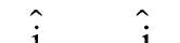
Unit vector in the direction of is
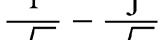
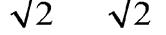
Unit vector in the direction of is
Electric flux, 2 52Nm/C EA φ=⋅=
Try yourself:
24. Point charges +2 µ C and –1 µ C inside a spherical surface and another point charge + 3 μC lies outside the spherical surface. Find the total electric flux passing through the spherical surface.
Ans: 1.13 × 10⁵ V-m
TEST YOURSELF
1. The electric field in a region of space is given by 52N/C ˆˆ Eij =+ . The electric flux due to this field through an area 2 m 2 lying in the YZ plane, in SI units, is
(1) 10 (2) 20
(3) 102 (4) 229
2. If a hemispherical body is placed in a uniform electric field E, then the flux linked with the curved surface is E
3. In a uniform electric field, find the total flux associated with the given surfaces.
a) E b) E c)
(1) a – 0, b – 0, c – 0
(2) a – 0, b – (πR2E), c – 0
(3) a – (2πRE), b – (πR2E), c – 0
(4) a – (πR2E), b – 0, c – 0
4. The electric field in a region of space is given by, 00, ˆˆ 2 EEiEj =+ where E 0 = 100 N/C. The flux of this field through a circular surface of radius 0.02 m, parallel to the Y-Z plane, is nearly:
(1) 3.14 Nm2/C (2) 0.02 Nm2/C
(3) 0.005 Nm2/C (4) 0.125 Nm2/C
Answer Key
(1) 1 (2) 2 (3) 1 (4) 4
1.10 GAUSS’S LAW AND ITS APPLICATIONS
In electrostatics, Gauss law is a powerful tool which is useful in simplifying electric field calculations where there is symmetry in charge distribution. This law can be used to find total flux associated with a closed surface. It can also be used to find how electric charge is distributed itself over conducting bodies. The statement of Gauss law is as given below
“The total electric flux through any closed surface is equal to 1 0 e times the net charge enclosed by that surface.”
Here, e o is permittivity of free space. If a closed surface S encloses an electric charge q, then according to Gauss’s theorem, the total electric flux through the closed surface is given by φ= ∈0 q
By definition, the total electric flux through the closed surface S is given by
where, E is electric field at the area element dS Therefore, Gauss’s theorem may be expressed as =
Hence, Gauss’s theorem may also be stated as below.
If a closed surface encloses a charge, then surface integral of the electric field (due to enclosed charge) over the closed surface is equal to 1 0 e times the charge enclosed.
1.10.1 Proof of Gauss’s Theorem
Consider a point charge q inside a closed surface ( A ) as shown. Imagine a sphere ( B ) of small radius r with charge q at the centre of the sphere. Electric field at any point on the surface of the sphere is,
Consider an element of area ds on the surface of the sphere.
Flux through that element, φ= dEds
(or) φ= 0cos0 dEds
( ∴ E and dS are both radially outwards) 22 11 ˆ . 44oo dqqrdsds rr φ== π∈π∈
∴ Total flux through the sphere is
φ=φ=
∴φ= ∈0 q
But flux through the sphere (B) is equal t o the flux through the closed surface (A) enclosing the sphere, because all the lines of force passing through the sphere (B) also passes through the closed surface (A).
The total flux through a cl osed surface is always 1 0 e times charge enclosed irrespective o f shape and size of the cl osed surfa ce and position of charge.
1.10.2 Explanation of Gauss’s Law
Consider charges q 1 ' q 2 ' q 3 ' ........ q n inside a closed surface and charges Q 1, Q 2 ,...... Q n outside that surface
Consider a point P on the surface. Let EEE n 12,, .... be the fields produced by q 1 , q2, q3,...qn at P and ′′′ EEE n 12,,.. be the fields produced by the charges Q1, Q2, ........ Qn at P. P q1 q3 q2 Q2 Q3 Q1 E
Now, the resultant electric field at P is given by
The flux of resultant electric field through the closed surface is EdsEdsEdsEds Eds n 12 1 ... ’ EdsEds n 2 ’’ ...
Here Eds 1 is the flux due to q1 which is ∈ 1 0 q and Eds 1 is the flux due to Q1 which is zero, as it is not enclosed by the Ga ussian surface. Similarly, the flux due to the other charges also can be written.
Now, we can write, Eds
. Edsq Σ ⇒=∫ε
enclosed
Here, Qenclosed ∑ is the sum of all enclosed charges which can be positive, negative or zero.
Key Insights:
■ The flux linked with any closed surface is not influenced by the charges present outside the surface.
■ But the electric field at any point is the net field due to all charges present inside as well as outside the closed surface.
1.10.3 Gaussian Surface
The expression for electric field intensity can be obtained by applying Coulomb’s law only in simple cases. In the situations, where
Coulomb’s law and principle of superposition becomes difficult in calculating the electric field, the same is achieved easily by using Gauss’s law. For this, one has to evaluate the surface integral.
To evaluate the surface integral easily, a closed surface is chosen cleverly around the charge distribution. The surface so chosen is called the Gaussian surface.
Thus, Gaussian surface around a charge distribution (may be a point charge, a line charge, a surface charge or a volume charge) is a closed surface, such that electric field intensity at all the points on the surface is same and the electric flux through the surface is along the normal to the surface.
1.10.4 To Deduce Coulomb’s Law from Gauss’s Law
Consider a point charge q 1 at O . Let us construct a Gaussian surface in the form of a closed sphere, having its centre at O and with a radius OP = r. Here, P is a point on the surface of that sphere.
This is the field intensity due to point charge q 1 at a distance r from that charge. If we keep a charge q 2 at P, the force acting between q 1 and q 2 is 12 22 0 1 , 4 FEqqq r == π∈ which is Coulomb’s law in ele ctrostatics.
Key Insights:
■ If a closed surface does not enclose any charge, then
The electric field strength at P due to charge q1 will be E which will be radially outwards. Let us consider a small area element ds at P on the surface of the sphere. ds will be along outward normal to the surface and is parallel to E . So we have EdsEdsEds cos. 0 This condition is applicable at every point on the surface of the sphere.
from Gauss’s law
i.e, if a closed body (not enclosing any charge) is placed in an electric field (either uniform on non-uniform), total flux linked with it will be zero. fE = 0 Sphere fE = 0
■ If a closed body encloses a charge q, total flux linked with the body will be
■ From this expression, it is clear that the flux linked with a closed surface is independent of the shape and size of the surface and position of charge inside it f E = (q/e o) f E = (q/e o) f E = (q/e o)
■ A hemispherical body is placed in a uniform electric field E. The flux linked with the curved surface, if field is (i) parallel to the base (ii) perpendicular to base and (iii) if a charge q is placed at its centre can be calculated as follows
Considering the hemispherical body as a closed body with a curved surface and a plane base (cross-section), the flux linked with the body will be zero as it does not encloses any charge i.e.,
φ=φ+φ= 0 CSPS ............. (1)
i) As field is parallel to base, the flux linked with base
φ=×π= 20cos900 PSER
Substituting this value of fPS in Eq. (1), we get: φ= 0 CS
ii) As field is perpendicular to base, the flux linked with base
φ=×π=−π202 cos180 PSERRE
So, substituting this value of f PS in Eq. (1), we get, φ=π 2 CSRE
iii) Total flux through the Gaussian surface (sphere) = 0 q ε
∴ Flux through hemisphere = 20 q ε
■ A point charge q is placed at a height a/2 exactly above the centre of a horizontal square plate of side a . Then flux linked with the plate is given by 60 q ε
Here Gaussian surface is a cube of side ‘a’ with the charge at its centre.
+q
a a a/2
Flux linked with Gaussian surface (cube) = 0 q ε
∴ Flux linked with given face = 60 q ε
■ A point charge q is placed at the open end of a cylinder as shown in figure. Then flux linked with it is given by 20 q ε
Here, Gaussian surface is a cylinder of radius r and length 2ℓ with the charge at its centre +q r
Flux linked with Gaussian surface (cylinder) = 0 q ε
∴ Flux linked with given surface = 20 q ε
Key Insights:
■ In case of closed symmetrical surface with charge at its centre, flux linked with each half will be 1()(2) 2 Eo q φ=∈ and if the symmetrical closed surface has ‘n‘ identical faces with point charge at its centre, flux linked with each face will be ()() Eo nqn φ=∈
■ If a point charge is kept at the centre of a cube, then the total flux linked with the cube is
φ= ∈0 1();totalQ Q
φ= ∈
Flux linked with each face of the cube is 0 1() 6 faceQ
■ If a point charge is kept at the centre of a face of the cube, the first we should enclose the charge by assuming a Gaussian surface (an identical imaginary cube)
(A) (B) Q
Total flux emerges from the system
(Two cubes)is φ= ∈0 total Q
Flux through the given cube is
φ= ∈ 20 cube Q
■ If a point charge is kept at the corner of a cube
26. The electric field in a region is given by 0 ˆ x EEi L = . Find the charge contained inside a cubical volume bounded by the surface x = 0, x = L, y =0 , y = L, z = 0 and z = L.
Sol. At x = 0, E = 0 and at x = l, 0 ˆ EEi = . The direction of the field is along the x-axis, so it will cross the yz-face of the cube. The flux of this field y z x x = L E o
φ=φ+φleftfacerightface = 0 + E0L2 = E 0 L2
By
Gauss’s
law, φ= ∈0 q
∴=∈φ=∈ 2 000 qEL
Try yourself:
25. A point charge q is placed at the centre of the edge of a cubical box. Find the total flux associated with that box.
Ans: /4 oq ∈
1.10.5 Applications of Gauss’s Law
(A) (B)
For enclosing the charge completely, seven more identical cubes are required. So total flux linked with the 8 cube system is
φ= ∈0 cube Q .
∴ Flux through the given cube cube 80 Q
φ= ∈ . and Flux through one face opposite to the charge, of the given cube is 0 face 0 /8 324 QQ ∈ φ== ∈
(Because only three faces are seen).
By applying Gauss’s law we can easily find out the electric intensity (or field strength) due to various kinds of charge distributions.
Electric Field due to a Point Charge
Consider a point charge q at point O to find electric field around it. Consider a spherical Gaussian surface of radius r around the charge with O as the centre. E ds q O r
At every point on this sphere, the electric field E has same magnitude and everywhere it is radial. If we consider an elemental area ds on the sphere, 0.cos0 EdsEdsEds ==
From Gauss’s law enclosed 0 s Edsq = ∫ε
2 0 .4 s EdsErq =π= ∫ε (or) = π∈ 2 0 1 4 Eq r
Field due to an Infinitely Long Straight Uniformly Charged Wire
Consider a thin infinitely long straight line charge having a uniform linear charge density λ placed along YY1. By symmetry, it follows that electric field due to line charge at a distance ‘r’ in any plane at right angles to the line charge is of the same magnitude and is directed radially outward.
To find electric field due to line charge at point P at a distance ‘r’ from it, draw a cylindrical surface of radius r and length l about the line charge as its axis (see figure). This cylindrical surface may be treated as the Gaussian surface for the line charge.
Let us now calculate the electric flux that crosses the Gaussian surface from the charge enclosed by the Gaussian surface. Since, electric lines of force are parallel to end faces (circular caps) of the cylinder, there is no component of field along the normal to the end faces. The electric flux crosses only through the curved surface of the cylinder, as the electric field due to the line charge is normal to the curved surface.
If E is the magnitude of electric field at point P, then electric flux through the Gaussian surface is given by
φ=× E area of the curved surface of a cylinder of radius r and length l or φ=×π 2 Er
According to Gauss’s theorem, we have φ= ε 0 q
Now, charge enclosed by the Gaussian surface, =λ
q
From equations (i) and (ii), we have
In contrast to electric field due to a point charge (which decreases inversely as the square of the distance from the charge), the field due to a line charge falls off as 1 r
If λ is positive, that is if the wire is positively charged, the direction of E will be radially outwards (perpendicular and away from the wire). On the other hand, if λ is negative, that is if the wire is negatively charged, the direction of E will be radially inwards (perpendicular and towards the wire). In both cases E will be perpendicular to the wire. Even though equation (iii) is derived for an infinitely long charged wire, it holds good approximately for electric field around the central portions of a long charged wire. This is because, the end effects can be neglected far from the flat end surfaces of Gaussian cylinder.
Electric field due to long uniformly charged conducting cylinder: Consider a long cylinder of radius R which is uniformly charged on its surface with charge density σ.
We know that at the interior points of a metal body electric field strength is zero. Let us find the electric field at a point which is at a distance r from the axis of the cylinder. Consider a cylindrical Gaussian surface of radius r and length L as shown in the figure.
From Gauss’s law, we can write, 0 1 .() enEdsq =
Here, enclosed2 qRL =σπ
Here, electric flux through the circular faces is zero. So, from Gauss’s law
Try yourself:
26. A very long uniformly charged metallise cylinder has radius R. Electric field at a distance R from the surface of the cylinder is E0. What is the electric field at a distance 2R from the surface of the cylinder.
Ans: 2 3 0E
Electric field due to uniformly charged nonconducting cylinder: Consider a long cylinder ρ of radius R charged with volume charge density uniformly. Let us find electric field at a distance r from the axis of the cylinder. Consider a cylindrical Gaussian surface of length L and radius r as shown. enclosed 0 . Edsq = ∫∈ ; where, 2 enclosed qRL =ρπ
The variation of E with distance r from the axis is as shown in the graph.
27. Electric field at a distance r0 from the axis of a very long uniformly charged cylinder is E0. What will be the electric field at a distance 4r0 from the axis of same cylinder?
Here, electric flux through the circular faces is zero.
Cases:
(i) If r > R, then from Gauss’s law, 2 0
(ii) If r = R, then ρ = ∈ 20 R E
(iii)If r < R, =ρπ 2 encl qrL
from Gauss’s law, 0 . enclEdsq = ∫∈
In vector form-, 20 r E ρ = ∈
The variation of E with distance r from the axis is as shown in the graph.
1 r = R
28. A non-conducting cylinder of radius R is uniformly charged with a volume charge density ρ C /m3. If electric field at its surface is E 0, find the electric field at a distance R from its surface?
To find electric field due to the plane sheet of charge at any point P distant r from it, imagine a Gaussian surface in the form of rectangular parallelopiped or cylinder of area of cross-section A passing through the point P. The electric lines of force are perpenducular to the flat end surfaces 1 and 2 and parallel to the remaining surfaces of the parallelopiped. So the flux due to electric field of the plane sheet of charge passes only through the two rectangular caps of the Gaussian surface.
Area = A Gaussian Plane sheet of charge
surface s
If E is the magnitude of electric field at point P , then electric flux crossing through the Gaussian surface is given by f = E × area of the end face (rectangular caps) of the parallelopiped.
or, f = E × 2A ..........(i)
Try yourself:
27. A non-conducting cylinder of radius R is uniformly charged with a volume charge density r C/m3. If electric field at its surface is E 0, find the electric field at a radial distance R/2.
Ans: E/20
Field due to a Uniformly Charged Infinite Plane Sheet (Non-conducting)
Consider an infinite thin plane sheet of positive charge having a uniform surface charge density r on both sides of the sheet. By symmetry, it follows that the electric field is perpendicular to the plane sheet of charge and is directed in outward direction.
According to Gauss’s theorem, we have enclosed 0 q φ= ε
Here, the charge enclosed by the Gaussian surface, enclosed qA =σ φ=σ ∈0 A ..........(ii)
From equations (i) and (ii), we have () 000 2ˆ or 22
where n is unit vector normal to the plane and away from it.
Thus, we find that the magnitude and direction of the electric field at a point due to an infinite plane sheet of charge is independent of its distance from the sheet of charge.
Key Insights:
■ The magnitude of electric field is independent of the distance from the sheet. This is true as long as the sheet is large as compared to the distance of the point from the sheet.
■ The above result holds good even for finite sheet of charge when the point is not nearer to the edge and the distance of the point from the sheet is small compared to the dimensions of the sheet.
■ If s is negative in the above case, E will be along the inward normal.
■ The magnitude of electric field of an infinite plane sheet of charge is independent of distance r from the sheet where as ∝ 2 1 E r in the case of point charge. The reason is that charge is not localised at a point but distributed on the sheet.
Electric Field due to Two Infinite Plane Parallel Sheets of Charge
i) In region I: The electric fields due to both the sheets of charge will be from right to left (opposite to the direction, in which distances are measured as positive). The electric field due to sheets A and B in region I will be
or, ()=−σ+σ ε 0 1 2 EAB ......... (i)
ii) In region II: The electric field due to sheet of charge A will be from left to right (along positive direction) and that due to sheet of charge B will be from right to left (along negative direction). Therefore, in region II,
0022 EAB
or, () 0 1 2 EAB =σ−σ ε ... (ii)
iii) In region III: The electric fields due to both the sheets of charge will be from left to right. i.e. along positive direction. Therefore, in region III,
εεε 000 1 222 AB EEAB ...(iii)
Special case: If σA= σ and σB=–σ, then it follows that electric field is zero in regions I and III, while in the region II, the electric field is given by
0 1 2 E (or) σ = ε 0 E
Consider two infinite plane parallel sheets of charge A and B, having surface charge densities equal to sA and sB, respectively. The two sheets divide the space in three regions, namely region I lying to the left of sheet A, region II between the sheets A and B, and region III to the right of sheet B, as shown in figure.
Thus, in case of two infinite plane sheets of charge having equal and opposite surface charge densities, the field is non-zero only in the space between the two sheets and it is constant i.e. uniform in this region. Further, the field is independent of the distance between the infinite plane sheets of charge
29. Two large non-conducting sheets A and B , having charge densities + 2 s C/m 2 and – s C/m2 are kept parallel to each other. Find electric field at point P Sol. EEEiii PAB 2 22 3 0020
A +2s –s y x P
Try yourself:
28. Three large non-conducting sheets A,B and C having charge densities 3 s C/m 2 , – s C/m2 and + s C/m2 are kept parallel to each other. Find the magnitude of electric field at P.
+3s +2s –s
Ans: 0 σ ε
Electric Field due to Infinite Conducting Sheet
Consider an infinite conducting sheet as shown. When charge is given to it, it distributes itself over the outer surface of the sheet. For a thin conducting sheet, the charge distributes on both of its faces. So, conducting sheet is equivalent to the combination of two non-conducting sheets, with the same charge density σ.
The electric field at any point is the superposition of the fields due to two nonconducting charged sheets.
Now, resultant field at P1 is,
σσσ =+=
∈∈∈ 1 00022 E
Now, resultant field at P2 is,
σσσ =+=
∈∈∈ 2 00022 E
Now, resultant field at P 3 is
σσ =−=
∈∈ 3 00 0 22 E
So, σ == ∈ 12 0 EE
Key Insights:
■ In case two infinite plane charged conductors of finite thickness are placed parallel to each other, the equations (i), (ii) and (iii) will modify to
()=−σ+σ ε 0 1 EAB ... in region I
()=σ−σ ε 0 1 EAB ... in region II and ()=σ+σ ε 0 1 EAB... in region III
30. Two large conducting plates A and B each of area A carrying charges +2 Q and – Q respectively, are kept parallel to each other. Find the electric field at P. Sol. EQ A Q A Q pA 2 22 3 0020
Try yourself:
29. Two large conducting parallel plates A and B having surface charge densities as shown in figure, are kept parallel to each other. Find the electric field at P
Field due to a Uniformly Charged Thin Spherical Shell (or Conducting Sphere)
Charged spherical shell Gaussian Surface
Consider a thin spherical shell of radius R and centre O. Let +q be the charge on the spherical shell. Let us find electric field at point P distant r from the centre of the spherical shell.
Cases:
■ When point P lies outside the spherical shell: Draw the Gaussian surface through point P. It will be a spherical shell of radius r and centre O
Let E be the electric field at point P due to charge q on the spherical shell. It is evident that the field due to charged spherical shell is radial and spherically symmetric. At every point on the surface of shell, the field has same magnitude and is along normal to the surface. Therefore, total flux through the Gaussian surface is given by
It is the same as that at distance r from a point charge q. It implies that for the points outside the charged spherical shell, the shell behaves as if the charge on the shell were concentrated at its centre. The above result for electric field due to a charged spherical shell can also be expressed in terms of its surface density as explained below.
If σ is uniform surface charge density of the spherical shell, then =πσ 42qR substituting for q in equation (i), we have
= ∈ 2 2 0 R E r (for r > R) or
Where r is position vector of the point with respect to centre of the sphere.
■ When point P lies on the surface of spherical shell: The Gaussian surface through point P will just enclose the charged spherical shell. Therefore, according Gauss’s theorem,
π= ∈ 2 0 .4 ERq (or) = π∈ 2 0 1 4 Eq R (for r=R) ...... (ii)
Since =πσ 42qR , the equation (ii) becomes σ = ∈0 E (for r=R) ...... (iii)
Since, the charge enclosed by the Gaussian surface is q , according to the Gauss’s theorem,
(or) σ = ∈0 ˆ En here n is the unit vector normal to the surface.
Key Insights:
■ For points outside and on the surface of a uniformly charged spherical shell, it behaves as if the entire charge on it were concentrated at the centre of the shell.
■ For points inside the charged spherical shell ( r < R ): Consider a concentric Gaussian surface with radius r < R as shown. We have, .42
Try yourself:
30. Surface charge density of a thin spherical metallic shell of radius R is σ. Find the electric field at distance 2R from the surface of the shell.
Ans: s /9 e 0
Electric Field due to a Uniformly Charged Non-conducting Solid Sphere
Consider a charged sphere of radius R with total charge q uniformly distributed in it. Here, volume charge density ρ= q V where V is
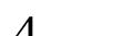
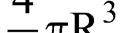
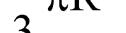

Cases:
i) For points outside the sphere ( r > R):
As P is inside the shell, there is no charge enclosed by the Gaussian surface as charge resides only on the outer surface of the shell.
From Gauss’s law, enclosed 0 .0 S Edsq==
E = 0 inside the charged shell.
31. Electric field on the surface of a charged conducting spherical shell of radius R is E0. Find the distance of the point from the surface of the shell, where the electric fields is E0 / 16. Sol.
Consider a Gaussian surface which is concentric sphere (around the charged sphere) with radius r > R.
From Gauss’s law, 0 . S Edsq = ∫∈ where, .42 S EdsEr ∫=π
ii) For points inside the sphere (r < R):
Let us consider a concentric Gaussian surface of radius r < R . Here also E will be radial everywhere but charge enclosed by the Gaussian surface is
3 enclosed3 4 3 qqr qrVR =×π=
From Gauss’s law, enclosed 0 . S Edsq = ∫∈
⇒π= ∈ 3 2 3 0 4 Erqr R and = π∈ 3 0 1 4 Eqr R
=ρπ
iii) At the centre of the sphere ( r = 0):
At the centre of the sphere, r = 0 E = 0
iv) On the surface of the sphere, r = R and = π∈ 2 0 1 4 Eq R
Key Insights:
■ In the case of a uniformly charged spherical distribution,(non conducting solid sphere)
i) For 2 0 1 , 4 rREq r >= π∈
ii) For 2 0 1 , 4 rREq R == π∈
iii) For 3 0 1 , 4 rREqr R <= π∈
iv) At the centre, r = 0, E = 0
■ The variation of E with distance r from centre is as shown in the graph.
If electric field at a distance R from its surface is E0, what is the electric field at a distance R/2 from its centre?
Sol. E R R R EREE o 0 3 2 0 0 3212 62 0 /
Try yourself:
31. A non-conducting solid sphere of radius R is uniformly charged throughout its volume. If electric field at a radial distance R/2 is equal to the electric field at a distance x from its surface outside the sphere, then find x
Ans: 21 R
Elec tric Field due to Concentric Conducting Charged Spherical Shells
Two concentric spherical conducting shells of radii a , b ( b > a ) have charges q 1 and q 2 respectively. Let us find the electric intensity and electric potential at a distance r from the common centre O.
Cases:
i) If r < a (i.e., for points inside the inner shell) qenclosed = 0, q2 b O a r q1 + + + + + + + + + + + + + + + +
∴×π== ∈ 2 0 1 400Er E = 0
ii) If r = a (i.e., for points on thin surface of inner shell) = 1 , enclosed qq
32. A non-conducting sphere of radius R is uniformly charged throughout its volume.
∴×π=⇒= ∈π∈ 21 12 00 11 4(). 4 EaqEq a
iii) If a < r < b (for points between the shells) enclosed q ε=
∴×π=⇒= ∈π∈ 21 12 00 114() 4 ErqEq r
iv) If r = b
[i.e., for points on the surface of outer shell]
=+12 enclosed qqq +
∴×π=+⇒= ∈π∈ 212 122 00 11()4(). 4 EbqqEqq b +
∈π∈ 212 122 00 11()4(). 4 EbqqEqq b
v) If r > b
[i.e., for points outside the outer shell]
=+12 enclosed qqq
∴×π=+ ∈ + ⇒= π∈ 2 12 0 12 2 0 1 4() 1() 4 Erqq Eqq r
33. Two concentric thin metallic spherical shells of the radius R and 2R carry charges + 2Q and Q respectively. Find the electric field at a distance 3R from their common centre.
Sol. If we consider a spherical concentric Gaussion surface of radius 3R, then Qenclosed = Q + 2Q = 3Q, By Gauss’s law, ERQEQR o 433 12 2 /02
Try yourself:
32. Two thin conducting metallic shells of radius R and 3R carrying charges +3Q and –Q respectively. A point charge +Q is placed at their common centre. Find the electric field at a radial distance 4 R.
Ans: 3 2064 Q R
Solid Angle
Solid a ngle is the three dimensional angle subtended by the lateral surface of a cone at its vertex
Solid angle Ω
Let us calculate the solid angle subtended by a surface X at a point O . Join all the points of the periphery of the surface x to the point O by straight lines as shown. It gives a cone with vertex at O. r2
x r1 S1 S2
By taking centre at O , we draw several spherical s ections on this cone of different radii as shown. Let the area of spherical section which is of radius r 1 be s 1 and the area of section of radius r2 be s2. The ratios of area of any surface intersected by cone to the square of radius of that sphere is a constant and it gives actually the solid angle Ω From the figure, solid angle subtended by surfac e X at the point O is given by 12 22 12 ss rr Ω== .
Key Insights:
■ SI unit of solid angle is steradian and it is a dimensionless quantity.
■ One steradian is the solid angle subtended at the centre of the sphere by the surface of the sphere having area equal to square of the radius of the sphere.
■ The surface subtending solid angle need not be normal to the axis of the cone. For example consider a surface X of area ds as shown. The axis of cone formed by the surface at O is not normal to the surface. In
this cone solid angle Ω subtended at point O can be given as θ Ω= 2 cos ds r
Here θ is the angle between ds and axis of the cone.
Relation between semi-vertex angle of a cone and solid angle subtended: Consider a spherical surface of radius R. Let X be a surface on that sphere which subtended a semi vertex angle θ (in radian) at the centre of the sphere. Now consider an elemental strip of this section of radius r = Rsinα and angular width dα as shown. Then surface area of this strip is given by () 2sin dsRRd =παα
The total area of spherical section can be obtained by integrating this elemental area from 0 to θ.
Total area of spherical section is,
Key Insights:
■ If Ω is solid angle subtended by this section at the centre O, then its area is given by =Ω 2 SR (as discussed earlier). So, we can write Ω=π−θ 222(1cos)RR and () Ω=π−θ 21cos
■ The solid angle subtended by a hemispherical surface at its centre is given by, Ω = 2π (1– cos 90°) = 2π steradians. If θ = 1800 in the previous case, we get the solid angle subtended by a closed surface, Ω = 2π(1–cos 180°) = 4π steradians
■ The total solid angle subtended by a closed surface is always 4π steradians, irrespective of the size and shape of the closed surface.
34. Two point charges +Q1 and –Q2 are placed at A and B respectively. A line of force emanates from Q1 at an angle θ with the line joining A and B. At what angle will it terminate at B? A + –B θf –Q2 –Q1
Sol. We know that number of lines of force emerge is proportional to magnitude of the charge. The field lines emanating from Q1, spread out equally in all directions. The number of field lines or flux through cone of half angle θ is Q1 4 21cos .
Similarly the number of lines of force terminating on -Q2 at an angle f is Q2 4 21cos . The total lines of force emanating from Q1 is equal to the total lines of force terminating on Q2
()()12 21cos21cos 44 QQ ⇒π−θ=π−φ ππ or ()() 121cos1cos 22 QQ−θ=−φ
θ=φ 22 12 sin/2sin/2QQ
φ=θ 1 2 sin/2sin/2 Q Q
11 2 2sinsin/2 Q Q
θ
Try yourself:
33. A point charge q is placed at a distance d from the centre of a circular disc of radius R . Find electric flux flowing through the disc due to that charge
1.11 METAL CONDUCTORS IN ELECTRIC FIELD
When metal conductor is kept in an electric field, there will be momentary flow of free electrons. After this flow stops, the conductor will be in electrostatic equilibrium. At such condition, conductor will have the following main properties.
TEST YOURSELF
1. Calculate the net flux emerging from the given enclosed surface, in Nm 2 C–1 +2C –3C +5C
(1) 4.5 × 10¹¹ (2) 45 × 1012
(3) zero (4) 1.12 × 10¹²
2. If the magnitude of electric flux entering and leaving an enclosed surface respectively is ϕ1 and ϕ2, the electric charge inside the surface will be
(1) (ϕ2 – ϕ1) e 0
(2) (ϕ1 + ϕ2)/ e 0
(3) (ϕ2 – ϕ1)/ e 0
(4) (ϕ1 + ϕ2) e 0
3. A charge Q is situated at the centre of a cube. The electric flux through one of the faces of the cube is
(1) Q/ε0
(2) Q/2ε0
(3) Q/4ε0
(4) Q/6ε0
Answer Key
(1) 1 (2) 1 (3) 4
■ Net electric field inside the conductor is zero. Let us consider a metal block kept in an external uniform electric field 0E . Due to this field each electron experiences force eE 0 in a direction opposite to 0E . This makes the electrons move to one face at which there will be net negative charge. As a result, on the opposite face there will be an equal positive charge. These charges are called induced charges. These induced charges establish an electric field iE within the metal which opposes the external field 0E . This applies a force on each free electron equal to eE i in the direction opposite to iE .
At equilibrium there will be no movement of free electrons and =⇒=00ii eEeEEE .
But iE and 0E are opposite in direction. So net electric field inside the metallic conductor is zero. () 00 iEE+=
(a)
(b)
■ The magnitude of electric field just outside the charged conductor is σ/ e o . where σ is surface charge density. This result is valid for conductor of any shape but preferably for large electric fields where the charge density on the conductor is high.
■ The net charge inside a conductor is zero. The charge resides on the outer surface of the conductor.
When a conductor is charged positively or negatively like charges repel each other. So, the charges try to get as far away from each other as they can. As a result, charges move to the surface of the conductor.
■ The electric field on the surface or just outside the charged conductor is normal to the surface of the conductor at every point. This means that component of electric field along the tangent to the surface is zero.
■ Electric flux inside the charged conductor is zero. As charge enclosed is zero, flux inside the conductor is also zero.
1.11.1 Cavity in the Conductor
We have discussed that there will be no electric field inside a charged conductor and all the charge resides on its outer surface only. Suppose, that charged conductor has a cavity or cavities and there are no charges within the cavity or cavities, even then charge resides on the outer surface of the conductor. There will be no charge on the walls of the cavity or cavities. This can be verified very easily using Gauss’s law by enclosing the cavity with a Gaussian surface
q = 0 (inside cavity)
Consider a conductor with spherical cavity inside it. There is no charge on the conductor. Now, a point charge +q is kept at the centre of the cavity. Due to this charge, a charge –q is induced on the inner surface of cavity . The total flux originated by + q will terminate on the cavity walls and no field lines enter into the conductor body.
For the dotted surface,
Fig. (a)
Fig. (b)
We can consider a Gaussian surface around the cavity and prove that induced charge on the cavity walls is –q. The reason is electric field (
E ) is zero inside the material of the conductor. The total enclosed charge within the Gaussian surface is zero. Here, the conductor is initially uncharged. From conservation of charge, we can say that on the outer surface of the conductor a charge + q will be induced. At any point inside the material of conductor, say at P, the electric field produced by + q in the cavity is cancelled by the field produced by charges induced on the walls of cavity and on the outer surface of the conductor.
If the point charge is not at the centre of the spherical cavity, even then induced charges on the cavity walls and on the outer surface of the conductor are –q and +q respectively. But the distribution of induced charges will change in such a way that at any point P in the material of the conductor resultant electric field is zero.
Suppose, the conductor has charge q0 on it initially. This charge resides on the outer surface of the conductor. If point charge q is kept inside the cavity, induced charges on the walls of cavity and on the outer surface of the
conductor are the same as before. i.e., –q and +q. But the total charge on the outer surface of the conductor is now ( q0 +q).
If the charge inside the cavity is displaced, the induced charge distribution on inner surface of the body changes such that at any point inside the material of the conductor resultant field is zero. In this case the charge distribution on outer surface of the conductor does not change and only the charge distribution on the cavity walls will change. Now, the charge inside the cavity is fixed. If another charge is brought towards the conductor from outside, it will not affect the charge distribution inside the cavity and only the distribution of charge on the outer surface will be affected.
1.11.2 Mechanical Force on the Charged Conductor
We know that like charges repel each other. So, when a conductor is charged, the charge on any point of the conductor is repelled by the charge on its remaining part. It means surface of a charged conductor experiences mechanical force.
Consider a charged conductor as shown. Let ds be the surface area of a small element on the conductor.
is the field due to the remaining surface of the conductor.
12EEE =+
But we know that σ = ∈0 E at P1, which is just outside the conductor and is zero at P2, which is just inside the conductor.
So, at P1, we have σ += ∈ 12 0 EE and at P2, we have E1 – E2 = 0
12 20 EE
Now, the force experienced by small surface ds due to the charge on the rest of the surface is
and
ForceF E Areads
1.11.3 Electric Pressure on a Charged Surface
From the above derivation we observed that a small surface of a charged conductor will experience a force by the remaining surface. The force per unit area of the surface is
Eor
This is known as electric pressure on the charged metal surface.
⇒=∈ 2 0 1 2 e PE
The electric field at point P1 near the conductor surface can be considered as the superposition of fields 1E and 2E . Here 1E is the field produced by that elemental surface and 2E
Suppose a charged body is in an external electric field. Let us find out the electric pressure on the surface of that charged body.
Consider a surface uniformly charged with charge density σ. On that surface ds is the surface area of a small element. The charge on that element is dq = σds.
E ds θ +s
The given surface is in an external electric field represented by the field lines as shown.
Let E be the intensity of electric field on the elemental surface. Here, angle E between and ds is . In this E has two components.


Component parallel to the surface is
||sinEE=θ and component normal to the surface is,
⊥=θ cos EE
Here, force due to E || on the surface is tangential which tries to stretch the surface, the force due to E ⊥ applies outward pressure on the surface. Now, outward force on the elemental surface is,
⊥⊥==σ () dFdqEdsE
So, the outwards electric pressure on the surface is,
⊥ ==σ⇒=σθ cos ee dF PEPE ds
35. A thin spherical shell radius of r has a charge Q uniformly distributed on it. At the centre of the shell, a negative point charge -q is placed. If the shell is cut into two identical hemispheres, still equilibrium is maintained. Then find the relation between Q and q? -q +Q R
Sol. Here the outward electric pressure at every point on the shell due to its own charge is
∈∈π 22 12 00 1 224 PQ r ; = π∈ 2 124 320 PQ r
Due to –q, the electric field on the surface of the shell is = π∈ 2 0 1 4 Eq r . This electric field pulls every point of the shell in inward direction. The inward pressure on the surface of the shell due to the negative charge is =σ 2 PE
22 0 1 44 Qq rr = π∈ 24160 Qq r
For equilibrium of the hemispherical shells ≥ 21 PP or ≥ π∈π∈ 2 2424 001632 QqQ rr ≥ 2 Q q
Try yourself:
34. If r and T are radius and surface tension of a spherical soap bubble respectively then find the charge needed to double the radius of bubble. Atmospheric pressure = P o
Apply Boyle’s Law.
Hint: Final pressure in the larger bubble PP T r P o o 2 24 2
Ans: 1287 00 12 TPrrr /
1.11.4 Unification of Electricity and Magnetism
In olden days electricity and magnetism were treated as separate subjects .Oersted, Ampere and Faraday proved that electric charges in motion produces magnetic fields and moving magnets produces electricity. The unification was achieved by Maxwell, this field is called as electromagnetism.
Every force that we can think of like friction, chemical force between atoms, forces between cells of living organisms have their origin in electro-magnetic force. Maxwell claimed that science of optics is related to electricity and magnetism.
Charged particles in motion exert both electric and magnetic forces. In the frame of reference where all the charges are at rest, the forces are purely electrical
TEST YOURSELF
1. A positively charged sphere of radius r 0 carries a volume charge density ρ. A spherical cavity of radius r0/2 is then hollowed out, and this portion is left empty as cavity, as shown.
C1 is the centre of the sphere and C2 is that
CHAPTER REVIEW
Electric Charges and Field
■ Electric charge is always associated with mass.
■ Electric charge is relativistically invariant.
■ Total electric charge is conserved.
■ Repulsion is a sure test to detect charge on a body.
■ Charge is quantised. Charge on a body is an integral multiple of the charge of an electron (1.6 × 10⁻¹⁹ C).
■ A stationary charge produces electro static field only.
■ A moving charge produces both electrostatic field and magnetic field.
Coulomb's Law
■ In vacuum, force between two point charges is given by
of the cavity. The direction and magnitude of the electric field at point B is
= Permittivity of free space is an electromechanical property of the vacuum.
■ In a medium other than vacuum
2 0 1 4 FQQ Kr = πε where K = dielectric constant of the medium.
■ For same electrostatic force between two point charges, 0 rKr = , where r = separation between same charges in a medium other than vacuum.
■ If a dielectric slab of thickness x and dielectric constant K is placed between two point charges kept at a separation r 0 in vacuum, then equivalent separation in vacuum 0(1) rrkx =+−
■ When two point charges Q1 and Q2 are kept at a separation d, then distance of the point from Q1 where the resultant electric field is zero is given by 2 1 /1xdQ Q
where + for like charges and – for unlike charges.
Electric Field Lines and Electric Field
■ Electric field lines are imaginary lines.
■ The tangent drawn to a field line at any point gives the direction of electric field at that point.
■ Number of electric lines of force emerging from a point charge Q is /0 Q qE
■ Two electric lines of force cannot intersect.
■ Two electric lines of force cannot touch each other.
■ Electrostatic lines of force do not form any closed loop.
■ Number of electric lines of force passing normally through unit area drawn around a point is equal to the intensity of electric field () E at that point.
■ Number of electric lines of force passing normally through a given area (A) is called electric flux. The electric flux ( f E)through that surface is E.EA φ=
■ A test charge (Q0) is a positive point charge and 00Q →
■ Intensity of electric field
N/C. F E Q
■ Intensity of electric field of a distance r from a point charge
■ Intensity of electric field on the axis of a thin charged ring of radius R at a distance x from its centre 223/2 0 1 4() EQx Rx = πε+
■ On the axis of a charged ring electric field is maximum at a distance /2 xR =±
■ Intensity of electric field at a point on the axis of a uniformly charged disc of radius R at a distance x from its centre is () 0 1cos 2 E σ =−θ ε where σ = surface charge density in C/m 2 R P x E C θ
Electric Dipole
■ A system of two equal and opposite charges separated by a small distance is called electric dipole.
■ An electric dipole is specified by dipole moment. p = 2aQ. Direction of p is from negative to positive charge p 2a –Q +Q
■ At an axial point, at a distance r from dipole centre, electric fields Epr ra 1 4 2 0 222 ..
■ For a small dipole ( a<<r) , at axial point Ep r 1 4 2 0 3 ..
■ At equatorial point at a distance r, Ep ra 1 402232 /
■ For a small dipole( a << r ) at equatorial point
Ep r 1 403..
■ At point P, Ep r 1 4 31 1 02 3 2 .costant andan
■ When an electric dipole is placed in a uniform electric field, making an angle θ with the field, the torque acting on the dipole is
pEpEandsin.
■ When a dipole is placed in a uniform electric field, force acting on the dipole is zero.
■ When a dipole is placed in a non – uniform field, force acting on the dipole is
Fp dE dr =
■ In a non-uniform electric field torque on the dipole may not be zero.
Gauss's law and its Applications
■ Net electric flux ( f E ) over a Gaussian surface is directly proportional to the net charge enclosed by the surface is
■ Over a closed surface
■ Electric field at any point on a Gaussian surface is produced by all charges lying inside and outside the surface.
■ Electric flux over a closed surface produced by all charges lying outside the surface is zero.
■ If an electric dipole is placed in a closed surface, then the flux over that surface is zero.
■ If a solid non- conducting sphere of radius R is uniformly charged throughout its volume ( r = charge density), then,