Industrial Automation
How to save energy in compressed air systems

Breakthrough engineering for a better world
How to save energy in compressed air systems
Breakthrough engineering for a better world
We create solutions for our customers which enable smarter, safer, more productive and sustainable factories, production lines and warehouse operations. Our pneumatic and electric motion systems help machine builders and end users around the world automate and optimise manufacturing and warehousing processes.
We have partnered with customers in industrial automation for over a century, applying our experience and innovation to create lasting value for their businesses. Our solutions support critical industries such as automotive, food and beverage, pharmaceuticals and even the space industry. We support the automation of precision manufacturing, product assembly, testing and packaging.
We use the latest digital technologies in our automation products and constantly innovate in close partnership with our customers. By applying our deep expertise, we can solve their toughest automation challenges, today and tomorrow. Through increased productivity, efficiency and safety, our customers can serve their own customers better, creating sustainable competitive advantage and delivering growth.
Our world-class product portfolio includes IMI Norgren, IMI Bimba, IMI Bahr and IMI Buschjost.
Breakthrough engineering you can count on.

At IMI, creating a better world is at the heart of our purpose and approach to working – which includes engineering sustainable solutions that benefit people, businesses, and the planet.
In this guide, we’ll demonstrate new ideas and methods to reduce energy consumption related to compressed air. Please refer to the appendix for calculations that can help you quantify your own compressed air needs and running costs.
But first, let’s examine why cutting down energy use is so important.
Cut CO2 emissions to reduce the impact of climate change
The UN Environment Programme Finance Initiative estimates that the industrial sector is responsible for 25% of global carbon dioxide emissions.
Industry’s significant energy consumption is a major part of this: the industry sector accounts for 25.1% of final energy consumption in the EU, making it the third-highest consumer after transport and households.
Our collective responsibility to reduce the impacts of climate change is forcing companies to grapple with their energy use and emissions.
But there are also more practical reasons for companies to reduce their environmental impact:
• Legislation
Stricter environmental impact policies limiting the amount of carbon dioxide they emit.
• Reputation
Avoiding reputational damage that can come from ineffective or nonexistent sustainability initiatives.

Global energy prices are likely to continue to rise. In other words, even if prices stabilise, industrial companies cannot afford to lose control of their energy spend. As a result, most companies are seeking ways to improve efficiency and reduce the amount of energy that is wasted.
Evolution of monthly average wholesale day-ahead baseload electricity prices in Europe in EUR2023/MWh, showing the European Power Benchmark
Source: Trinomics et al. (2024). Final Report – Study on energy prices and costs: evaluating impacts on households and industry’s costs – 2024 edition (p. 33, Figure 3). European Commission, Directorate-General for Energy.
Share of electricity consumption in Germany by consumer groups 2023
Average electricity consumption of a company for compressed air 2023
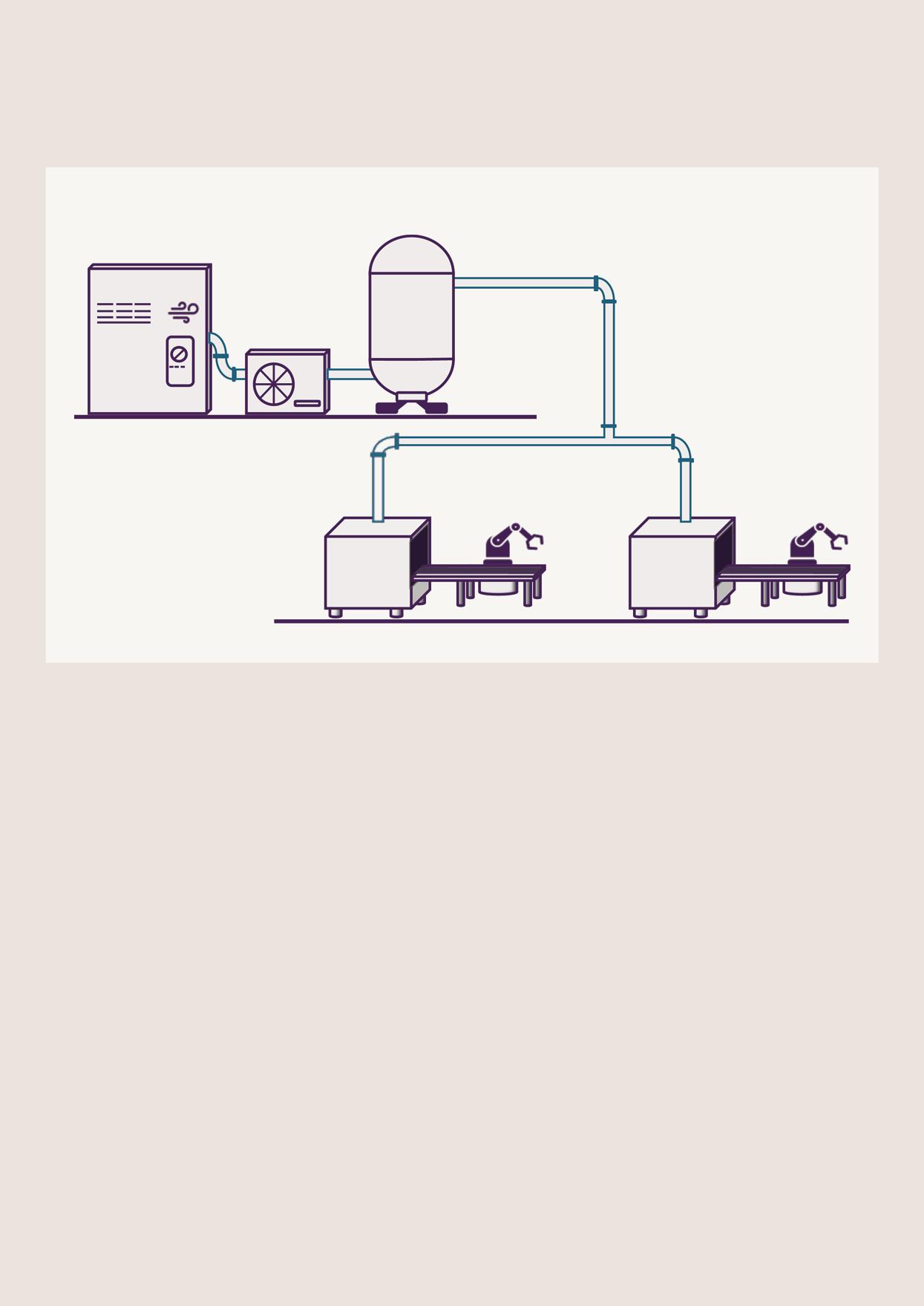
A compressed air system consists of three key parts: generation, distribution, and consumption. Substantial cost savings can be achieved when designing a completely new machine, retrofitting an existing system, or optimising maintenance practices.
New machine or process design
New machines can be optimised from the outset by utilising the ideal combination of components.
Indicative Compressed air costs
Maintenance and retrofit
Installed machines or compressed air lines can be upgraded with new components – for example, installing an energysaving circuit.
€0.02/m3 (at energy price €0.20/kWh with a 7 bar operating pressure)
Compressed air is typically generated using electrically driven compressors.
Optimising compressed air at the point of generation is the first opportunity to improve system efficiency.
The most common types of compressors are:
• Piston compressors
• Screw compressors
• Rotary vane compressors
• Turbo compressors
• Scroll compressors
The main components directly downstream of the compressors, feeding into the downstream compressed air system, are compressed air dryers, compressed air filters, and compressed air storage.
The receiver, a compressed air storage device, serves as a buffer, and compensates for fluctuations in compressed air demand, absorbs compressed air peaks, relieves compressor load, and is an important component in optimising energy consumption.
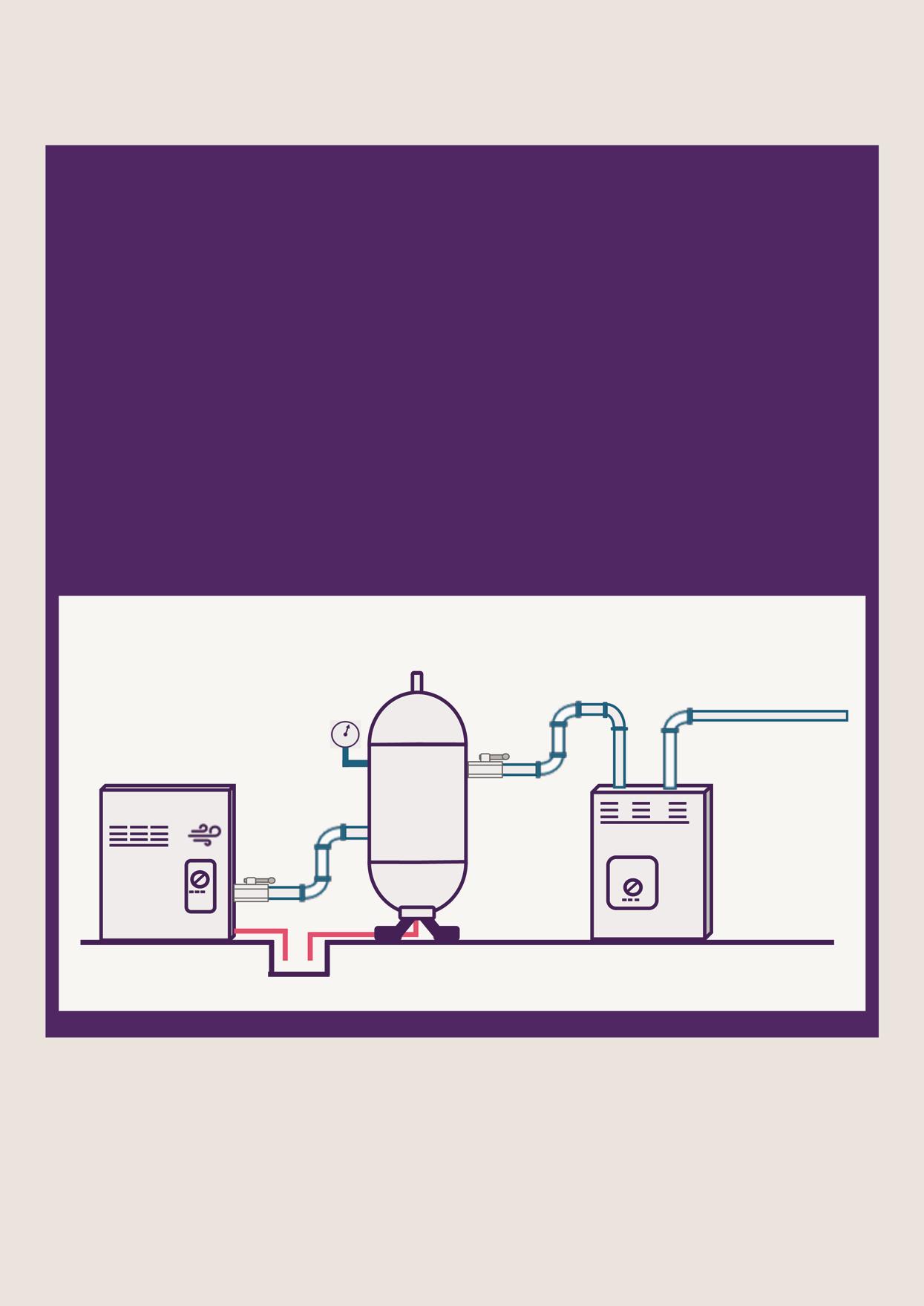
To operate at peak efficiency, all system components, including any compressed air consumers connected to the system, must be of the correct size.
When sizing components, consider both the flow rate and pressure requirement placed upon the compressed air system.
Sequences of compressed air generation:
1. Standard recommendation:
Compressor & Aftercooler
Compressed air storage
Dryer
Filter
Advantages: Less residual moisture reduces the dryer’s load and protects the filters, resulting in longer maintenance intervals and improved energy efficiency.
2. Alternative sequence
Compressor & Aftercooler
Dryer Filter
Compressed air storage
This setup has pros and cons: cooling in the storage may cause condensate that bypasses filters and reaches consumers. However, it can also protect the application when air demand exceeds the dryer’s capacity.
It is important to consider potential system expansions and bear in mind the importance of appropriate maintenance for keeping compressors and pneumatic components working efficiently.
How does it work? The compressor is sized to accommodate the maximum expected flow.
The compressor runs at fixed speed. It switches between full load (100% flow) and idle (0% flow).
Energy consumption Even in idle mode, electrical energy is consumed.
When should it be used?

Intelligent control systems adjust the compressor motor speed precisely to match the required compressed air flow.
Energy consumption closely matches actual demand, improving efficiency.
Systems with relatively stable air demand. Systems with highly fluctuating air demand. Can be used in combination with full load/idle compressors.
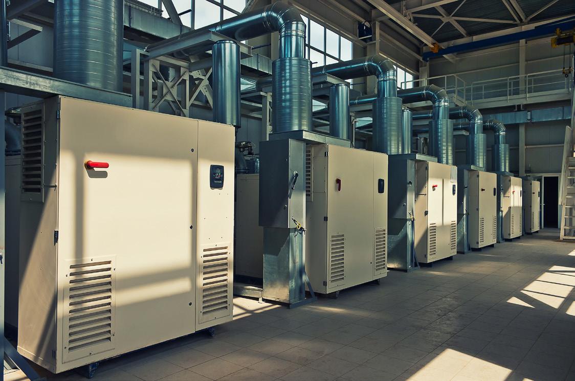
Instead of releasing waste heat into the atmosphere, over 90% of the energy absorbed by a compressor—typically converted into heat—can be recovered and repurposed. By integrating an appropriate cooling system, this waste heat can be utilised for other processes, such as heating adjacent buildings, supporting production processes, or providing domestic hot water through heat exchangers. This approach not only reduces the need to generate additional energy but also lowers energy costs, improves overall system efficiency, and minimises the CO 2 footprint.
Example: Directing waste heat through heat exchangers for use in production processes.
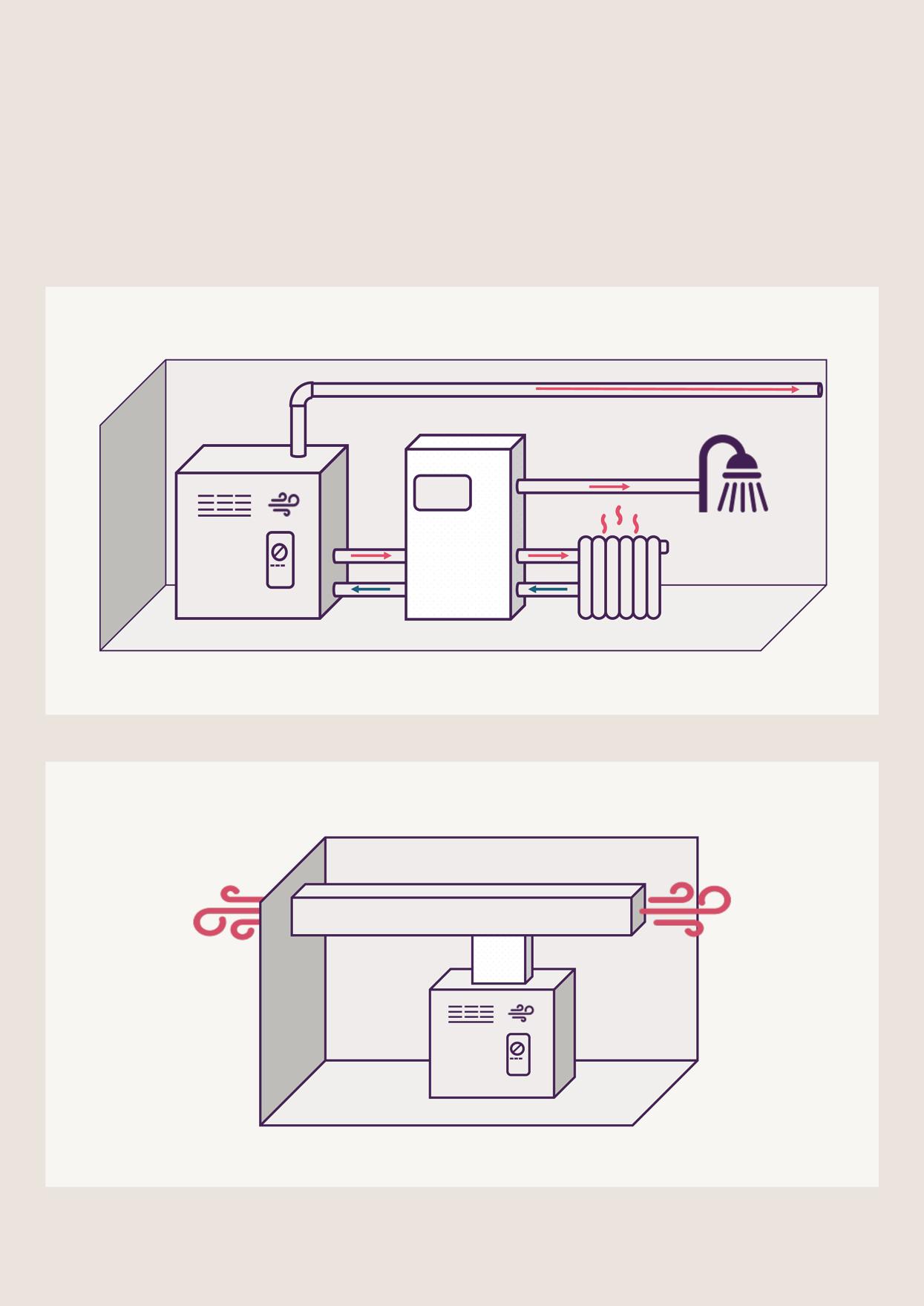
Compressor
Heating system
Example: Using warm exhaust air to heat adjacent buildings.
Following best practice for sizing, length, and installation configuration of compressed air distribution systems minimises pressure drop and improves energy efficiency.
Here are some best-practice checks to make within a distribution system:
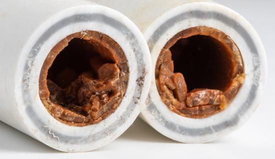
Are tubes and pipes free of corrosion and dirt?
If pipe scale builds up, it can reduce the diameter of the system’s tubes or pipes. As a result, the pressure in the system may need to be increased in order to reach the same flow rate.
This is obviously a waste of energy – replacing these tubes and pipes is an opportunity to upgrade to polymer tubing. Conducting regular maintenance to avoid contamination build-up helps reduce energy consumption.
Dirt and rust can also damage components like cylinders and valves in the system. This can, in turn, increase the likelihood of faults and leakages, both of which waste air and drive up energy bills.
Is the compressed air system arranged in the optimum ring main configuration?
Arranging tubes or pipes in a ring main configuration allows air to flow in both directions towards the same endpoint, which balances air pressure across the system.
Bigger facilities should choose configurations that feature multiple interconnected rings. This is referred to as zoning.
Individually zoned ring mains can be isolated or shut down when not in use, providing greater control of energy use and supporting safe maintenance practice.
Is the main line correctly dimensioned?
Undersized main lines may fail to support the flow rate required by the entire system, introducing unnecessary resistance that results in pressure drops. Compensating for these pressure drops further increases energy consumption.
System expansions can lead to this, so it is important to consider future plans when calculating ring main pipe diameter requirements.
Have steps been taken to identify and minimise leaks?
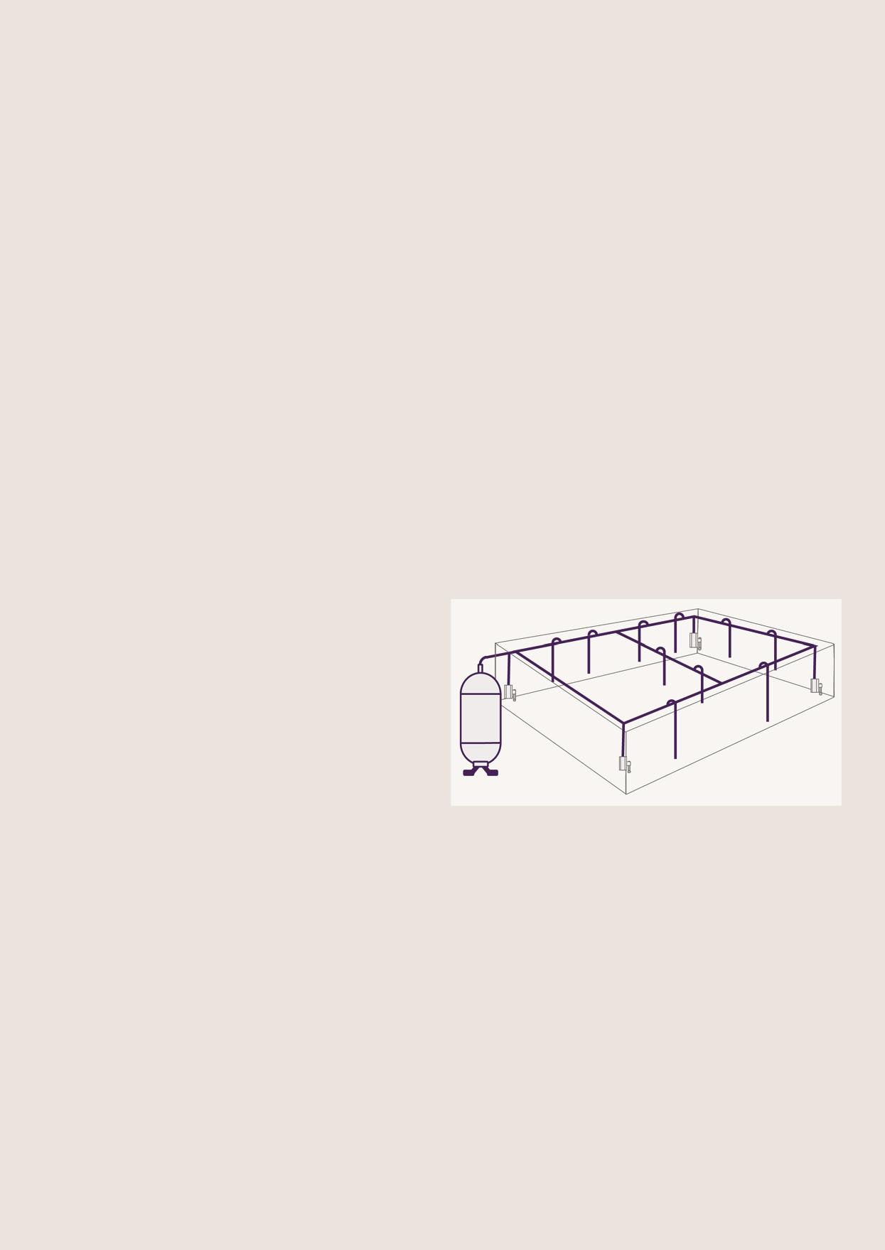
Ring-line
Shut-off valve
Reduce pipe length to avoid unnecessary friction and pressure drop
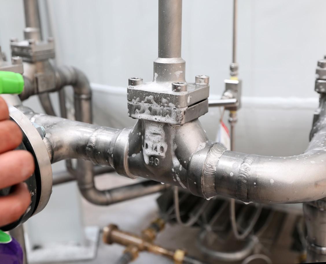
Air leaks are a major source of waste in compressed air systems, but they’re often difficult to detect with the naked eye.
To address this, install pressure and/or flow sensors that can alert maintenance teams to air leaks within a distribution system. On top of this, it’s a good idea to regularly run routine inspections, so leaks are fixed before they waste too much compressed air.
There are several ways to reduce or fix leaks, from choosing good-quality components to simplifying the setup of the system. We’ll talk more about this later in the guide.
Energy is typically consumed by:
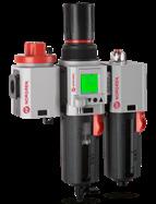
• Air preparation
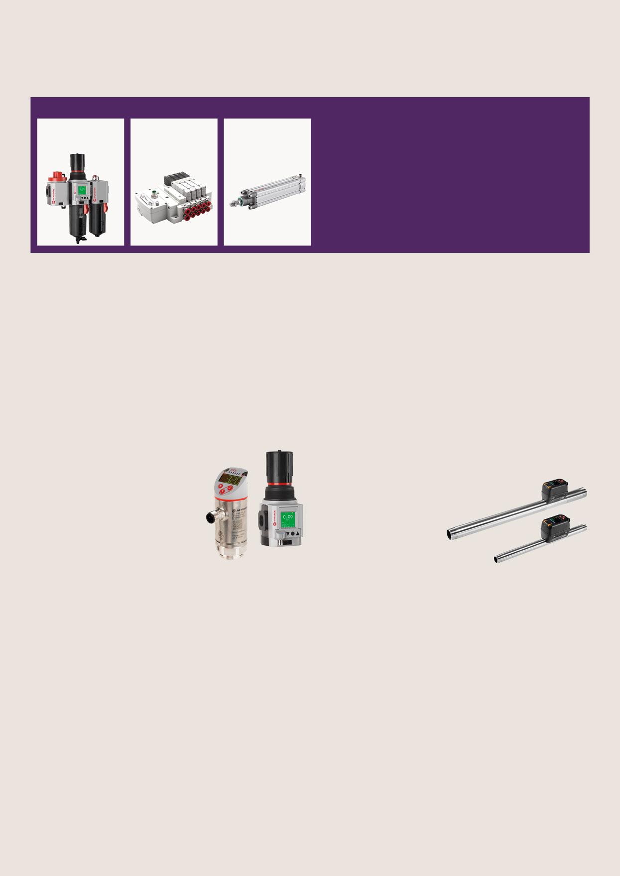
• Control
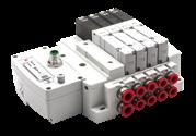
• Movement
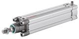
To reduce the amount of energy a system uses, consider:
• Identifying and avoiding leaks
• Identifying and preventing pressure drop
• Correct sizing and dimensioning
• Preventive maintenance
• Misuse of compressed air
• Pressurisation
Maintaining the right pressure and flow in a compressed air system is crucial:
On average, every additional one bar of pressure increases a plant’s energy costs by 7%
Tracking pressure and flow rate is essential for identifying and fixing pressure drops at the point of consumption; they are also important efficiency metrics to establish:
• Pressure measurement
Automatic pressure level monitoring in pneumatic systems can provide alerts to changes that might indicate an issue.
• Flow measurement
Continuous monitoring of a zone, production line, or machine to gather flow data allows for consumption and leakage assessment. Tracking compressed air use over a period of time helps establish baselines for normal performance and indicates issues faster.
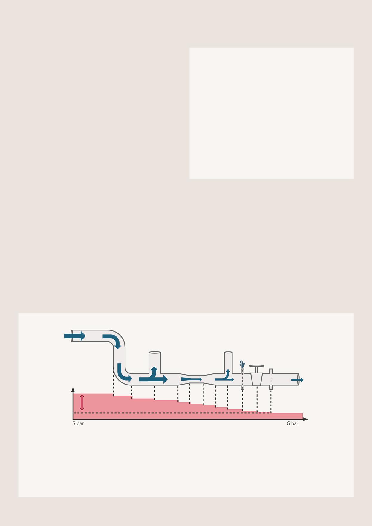
Pressure drop can be defined as the loss of available power in a system. In practice, it manifests as low pressure in parts of the system.
It is often compensated for by increasing the pressure setting. But every unnecessary pressure drop of 1 bar results in a 7% increase in generation costs.
Typical measures to reduce pressure loss include:
• Correct sizing (devices, tubes, consumers, connections)
• Avoiding leaks
• Preventive maintenance
1. Choose the right tube/pipe cross-section for the system’s flow rate.
2. Build in straight lines, wherever possible.
3. Reduce the number of line connections to the minimum.
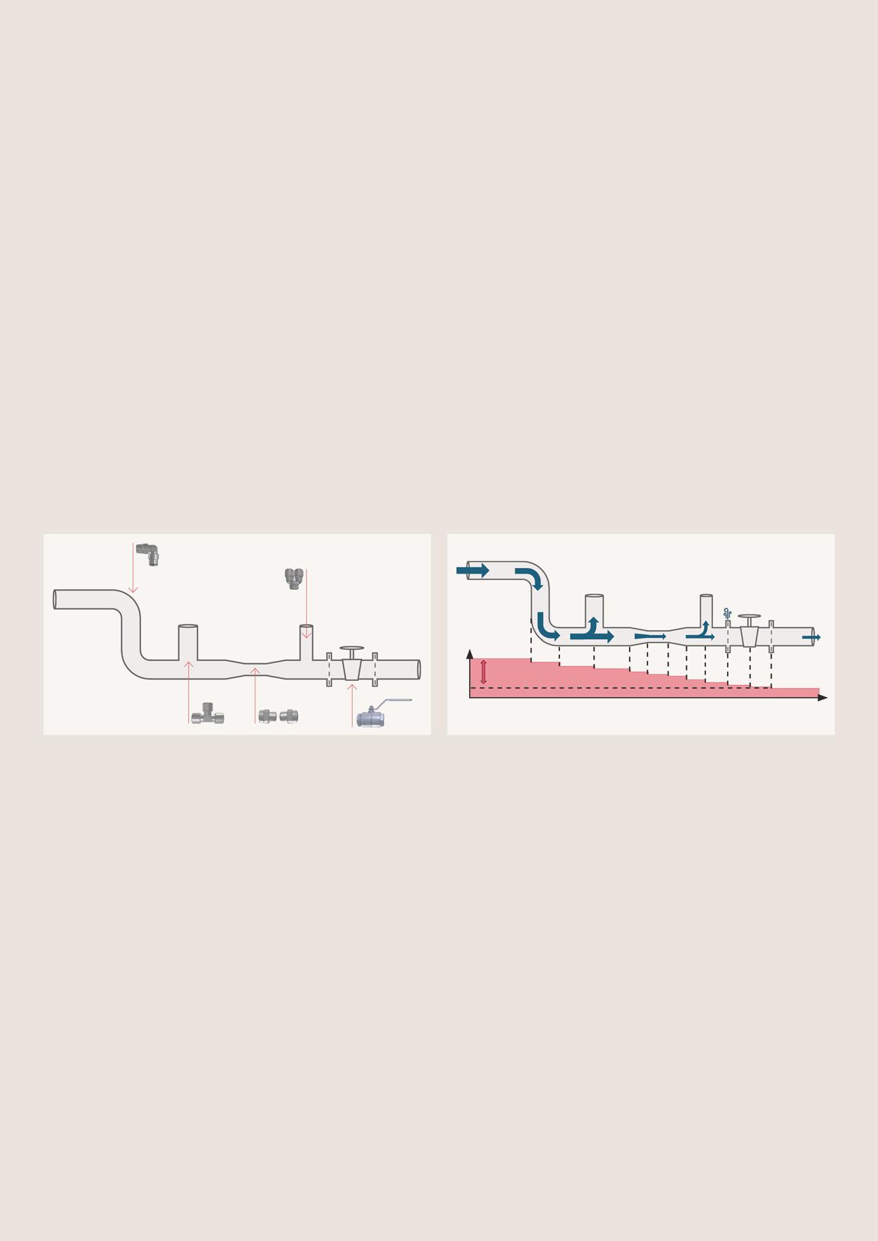
4. Avoid unnecessary changes to tube/pipe sizes.
5. Reduce tube lengths.
6. Where tube splitting is required, where possible use Y splitters ahead of T to minimise flow reduction
* Self exhausting – full open
Example: an 8mm 45° elbow fitting causes same pressure drop as 0.15m long 8mm tube.
Maximum Recommended Flow*
*Air flow rates in dm3/s free air at standard atmospheric pressure of 1,013 mbar.
General notes
The flow values are based on a pressure drop (ΔP) as follows:
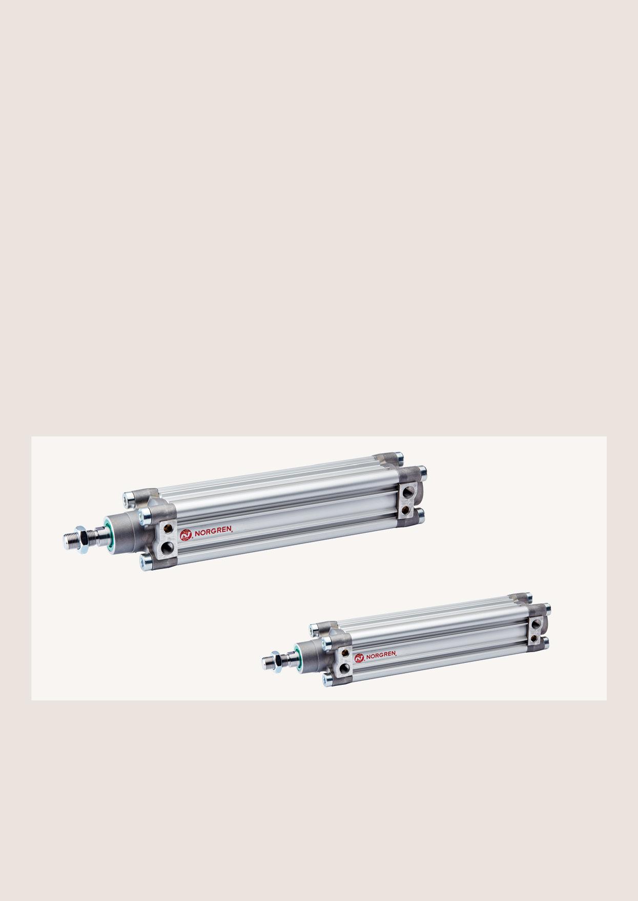
Actuators are typically used to provide motion and force in industrial automation applications.
Sizing an actuator appropriately to meet the application requirements is crucial for energy efficiency.
Oversized actuators consume more air than necessary, reducing the system’s overall efficiency. On the other hand, undersized actuators may not provide the required force, leading to process performance issues.
1. Calculate the Load in Newtons: Start with the load in kilograms. Multiply the load by 9.81 to convert it into Newtons (force).
2. Apply a Safety Factor:
Add a safety margin based on the type of load:
a. For dynamic loads, add 50%.
b. For static loads, add 5%.
3. Determine the Minimum Thrust Requirement: The result is the minimum thrust needed for the actuator.
4. Verify in Technical Documentation: Cross-check this value with the actuator specifications provided in the technical support documentation.
Most catalogues and technical brochures quote actuator thrust based on a pressure of 6 bar. If the actuator will be used at a different pressure, the calculation must be adjusted as follows:
• Take the thrust value quoted in the catalogue.
• Divide this value by 6 (to normalise it to 1 bar).
• Multiply the result by the actual air pressure (in bar) that will be used.
This calculation provides the adjusted thrust figure for the actuator at the specified operating pressure.
Valves are typically used to block or divert the flow of compressed air in industrial automation applications. This compressed air can be used to move a cylinder, air tool, or air motor directly, or pilot another part of the system.
The considerations for the correct sizing of a pneumatic control valve are:
1. Understanding flow rate needs of downstream pneumatic components. Refer to valve datasheets to guide selection of valves with appropriate flow rate (l/min) capacity.
2. Choose solenoid valves with the most energy-efficient power consumption – remembering to take the needs of the application into account.
The finer the filter element, the greater the pressure loss and the higher the energy costs.
That’s why it’s essential to select the correct filtration grade for your application. Always choose a filter that is appropriately sized to minimise pressure drop and meet the required flow and pressure.
Properly dimensioned filters reduce energy costs, extend service life, and improve overall efficiency.
In some cases, a modest oversizing of the filter can further help achieve these benefits.
Use flow curves provided in product data sheets – such as those show here for the Excelon® Plus F84G (Standard Filter) –to ensure accurate filter selection.
Further information: https://www.norgren.com/en/support/blog/ how-to-choose-the-correct-filtration
Leaks can be a significant source of wasted energy in an industrial compressed air system.
If compressed air were hydraulic fluid, leaks would be visible and more likely to be quickly fixed. As it is, a low-level hiss in a factory can be accepted as ‘part of the job’. With compressed air’s price being roughly comparable to that of domestic gas, this attitude costs industry dearly.
In addition to being a source of wasted energy, leaks can also contribute to other operating losses. Leaks cause pressure loss in systems, which can mean pressure is too low for an application to run as intended, potentially leading to a reduction of quality and rejected product. Frequently, the system pressure is increased to compensate for the leaks rather than simply fix them.
Use the charts below to evaluate how leakages could affect a specific system.
Leakages
* Please refer to the Orifice Flow Chart for values.
Orifice Flow Chart
Ageing pipework
Ageing pipework is a prime source of leaks. Replace anycorroded pipework sections - for safety as well as energy saving.
Old components
Check old pneumatic components like cylinders and regulators for worn internal air seals. These can cause large leaks.
Fittings, flanges, and manifolds
Look at the connection points in the main distribution system and any offshoots. These are potential weak points in the system.
This is particularly common when several snap connectors are used together to form manifolds. In these situations, worn connectors and poorly joined pipework can be a source of leakage.
When drain valves are stuck open (or even left open intentionally), large amounts of air will escape from the system.
Make sure to keep a close eye on remote parts of the system since this is where condensate often collects.
couplings
Leaks can be caused by damage to the tubes in a system.
Check for abrasion from surrounding objects and deterioration of the tube material. If the tube is too long or too short, this can also cause strain on the tube joint.
Systems left pressurised when not in use
Some leakage is hard to avoid in pressurised dormant systems. Best practice is to safely depressurise when not in use.
The impact can be reduced by isolating from the air supply when not in use.
Use simple shut-off valves or electrically operated soft start dump valves to achieve this.
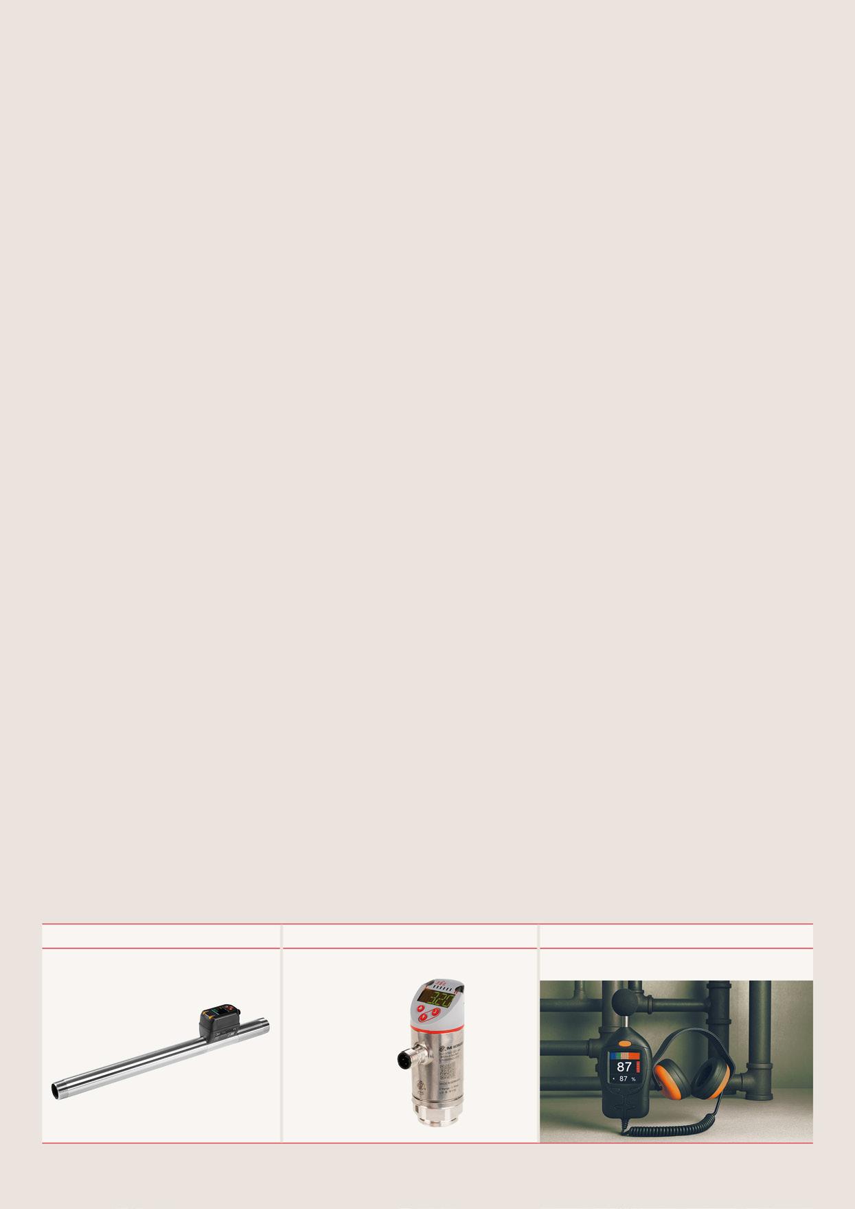
Flow sensors play a key role in monitoring and optimising compressed air systems, providing valuable data that can form the basis for energy savings. They can be integrated into machine and process design from the outset or used as an
audit tool for existing installations. In-line flow sensors continuously monitor critical process parameters, including air flow rate, pressure, and volume, helping to identify pressure drops and detect airflow leaks.
A precise inline flow sensor for energy management.
Continuous monitoring
Equipped with multiple sensors for real-time data on flow rate, pressure, total consumption, and temperature.
Minimise pressure drop
Inline design minimises pressure drop, providing accurate insight without increasing energy costs.
IO-Link capability
Supports remote setup and provides more detailed application performance data.
Totaliser function
Monitor air usage in real-time, revealing signs of leakage and making it easier to assign utility costs.
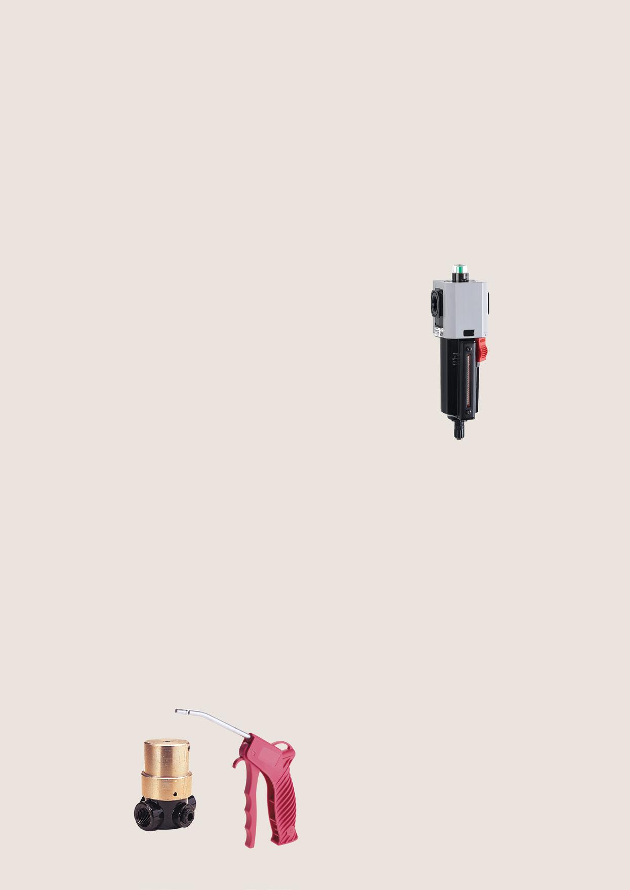
Filter elements in standard or coalescing filters become clogged over time, especially in applications with lower air quality. This leads to increasing pressure drops, requiring higher outlet pressure to compensate, which in turn drives up energy consumption and costs.
Why is it important?:
• Regular maintenance ensures optimal performance and energy efficiency.
• Clogged filters increase energy consumption and operating costs.
How to fix it:
• Use mechanical indicators or electrical differential pressure switches and sensors to monitor filter condition.
• Replace general-purpose filter elements at a differential pressure of approximately 0.7 bar.
• For coalescing filters, pressure drop indicators are recommended to maximise element life.
• Change filter elements regularly and service them at least annually.
• Without indicators, annual servicing is the minimum recommendation.
What about carbon filters?
• Carbon filters, being adsorption filters, require different maintenance.
• Replace activated carbon filters every 1,000 operating hours, though this may vary depending on application conditions.
Product Spotlight
• Excelon® Plus – designed for effective and efficient filtration.
Compressed air is often used for processes such as cleaning and drying individual components, blowing off workbenches, or clearing other surfaces
Why is it important?:
Compressed air is frequently misused as blow air, despite the availability of simpler and cheaper alternatives. This results in unnecessarily high energy consumption and costs. Additionally, issues such as excessive leaks, suboptimal line dimensions, and pressures that are too high for the application further contribute to energy waste and increased operational expenses.
How to fix it:
• Explore alternatives to blow air, reserving compressed air for applications where it is truly necessary.
• If compressed air must be used as blow air, reduce wastage by using energy-saving components such as energy-efficient nozzles and blow guns. These ensure optimal pressure is applied without over-pressurisation.
• Use preset regulators, such as the IMI Norgren R16 series, to lower air pressure and support safe working practices.
• Regularly inspect and address leaks, and ensure pneumatic lines and components are properly dimensioned to minimise pressure losses.
Pressure setting
Pressure regulator
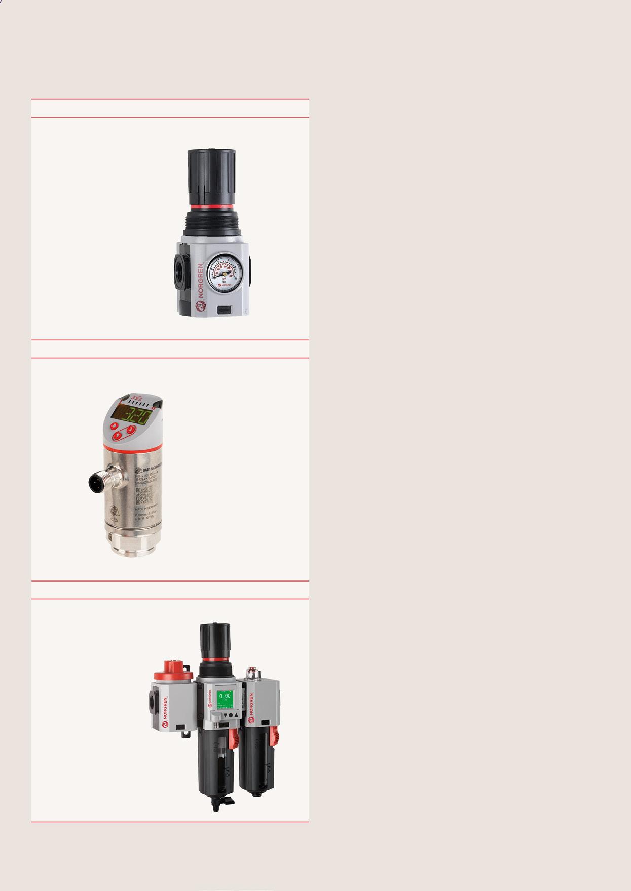
Plus R82 or R84
Pressure measurements
Pressure sensor / switch
Pressure setting and measurement
Electronic Pressure Sensor
Compressed air systems often operate from a central supply line, with multiple consumers or applications branching off, each with varying pressure requirements. The pressure in the main line must be set to meet the needs of the application with the highest pressure demand. However, running all applications at this maximum pressure is energy-inefficient, increases wear, and can even cause damage by exceeding the permissible pressure for some consumers
Operating all applications at the same high pressure wastes energy and increases operational costs. It also accelerates wear on components and risks malfunctions or damage to equipment that cannot handle excessive pressure. Additionally, pressure losses in the system, caused by factors such as line dimensions and flow rates, can require higher supply pressures to maintain adequate pressure at the point of use.
How to fix it:
• Install point-of-use pressure regulators to set pressures only as high as required for each specific application or consumer.
• Every 1 bar of pressure reduction can save up to 7% in energy costs.
• Minimise pressure losses by optimising line dimensions, reducing flow restrictions, and maintaining the system properly.
• Consider designing the main supply line as a ring line to improve efficiency and reduce pressure drops.
Use of proportional control valves can provide in-process optimisation by adjusting pressure and/or flow to match specific application requirements at any given point in time.
Two IMI Norgren products support this:
Proportional pressure regulators
Adapt output pressure in systems with fluctuating loads, ensuring stability and efficiency.
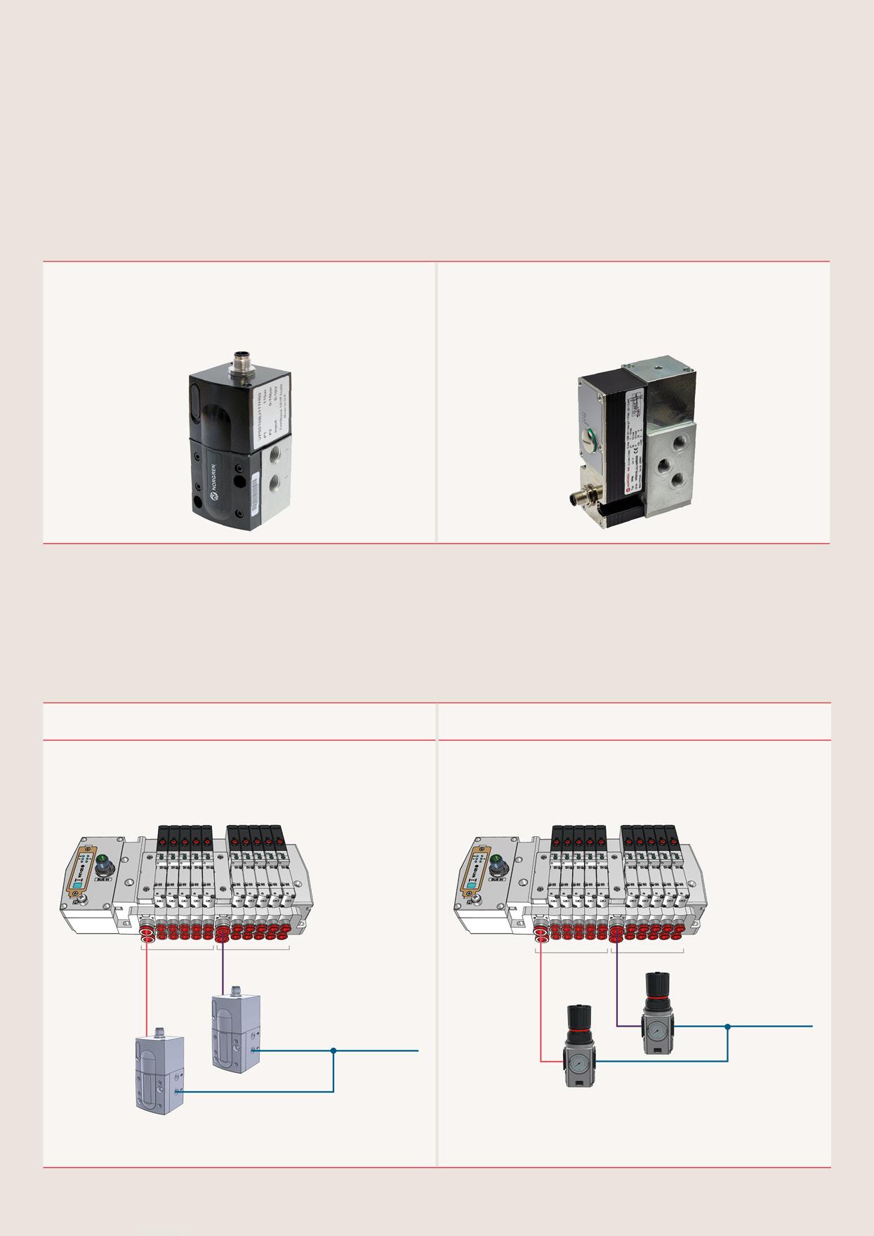
Proportional flow regulators
Ideal for applications needing variable speed control, such as speed profiling on actuators. They provide smooth operation across different speeds.
By using proportional valves, it is possible to maintain efficient operations, minimise energy waste, and avoid potential component damage, ensuring the system runs optimally under varying conditions.
Working with different pressure zones is an effective way of saving energy.
For applications that require frequent pressure changes For static dual-pressure requirements
Products shown:
Proportional control valve VP50
Valve islands VR
Products shown:
R82R pressure regulator
Valve islands VR
Example: Zone 1 operates at 6 bar, while Zone 2 only requires 4 bar for its downstream components.
This dual-pressure system uses:
• 102GB or
• R82R*
• R74R*
*Reverse flow regulators, only to be used between valve and actuator.
Reducing the pressure of the return stroke saves a significant amount of energy and money.
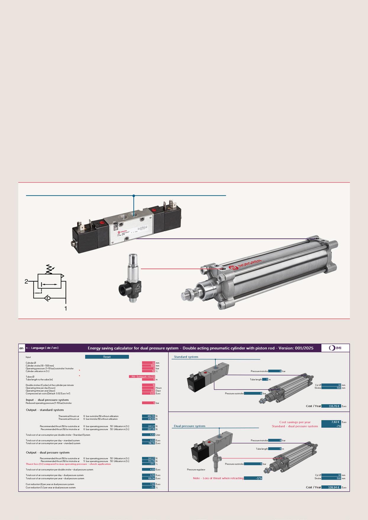
Every pressure reduction of 1 bar results in a 7% energy saving
Take a look at the example calculation below.
This dual-pressure system uses VS series/sandwich components. Once again, reducing the pressure of the return stroke can save a significant amount of energy and money.
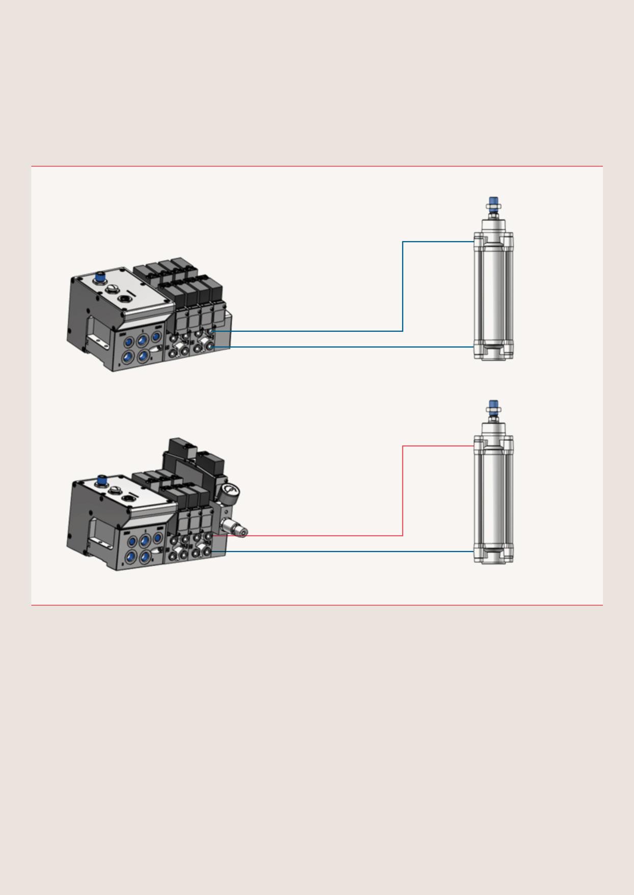
Integrating sandwich pressure regulators into a valve island can help save space where application constraints require a compact system build.
Forward thinking businesses are taking important steps to minimise not just costs – but also their environmental impact. The IMI Norgren integrated valve and actuator control, or IVAC offers a powerful solution that delivers on both fronts. IVAC combines a control valve, position sensors, speed controls, and an ISO-standard actuator into a single, compact unit.
• Complete integrated solution
• Saves air and saves costs
• Conforms to ISO 15552 footprint
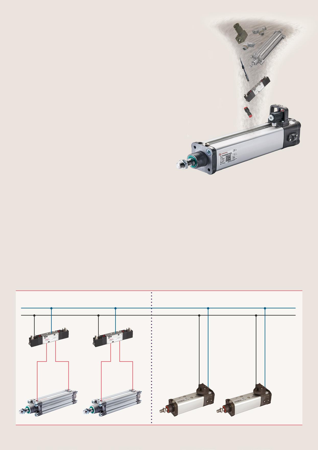
Integrated solution
Eliminates tubing and connections between valve and cylinder
Minimal dead volume and no exhaust of unused volume
Energy saving of up to 50%
The chart depicts the typical energy saving potential from switching to an IVAC compared to a convention valve-actuator assembly. For a more precise estimate of savings unique to your application, try our online Energy saving calculator!

Link to calculator:
20.000
Calculation based on: 6 bar operating pressure, assuming 5m installation length between valve and actuator with conventional separate arrangement, 30 cycles/min, 8 hours/ day, 225 days/year and compressed air cost of 0,02€ per m3
10.000
Outdated equipment and leaky pipelines cause an unnecessary increase in energy use. Additionally, air leaks force the system to run harder and longer to meet demand. These factors lead to increased carbon emissions.
Large amounts of oil-infused condensate are another problem with oil-based compressed air systems. Properly managing waste can greatly benefit aquatic life, keep our waterways clean, and protect human health.
Auditing
A quarterly or biannual assessment of the compressed air system can reveal leaks that have been increasing energy use and damaging the environment.
Routine monitoring, filter replacement, and servicing guarantee optimal air quality, lower pressure drops, and fewer leaks.
IMI Norgren M/80 inline flow sensors, in particular, can give actionable, real-time data to assist in swift detection and repair of leaks.
Older electric motors, compressor rotors, and other components may become environmental hazards. Replacing or repairing compressors with environmentally friendly equipment not only reduces emissions but also increases energy efficiency.
On a global scale, the United Nations’ 2030 Agenda for Sustainable Development outlines various goals for increasing sustainability, as well as broader agenda items addressing human rights and other global issues.
Industrial facilities that connect their operations with the UN’s 2030 Agenda can play a critical role in attaining a sustainable and eco-friendly future while saving money.
Goal 7: Ensure access to affordable, reliable, sustainable, and modern energy for all
Industry should concentrate on energy efficiency, encouraging a shift to renewable energy, and improving technology for greener energy. Addressing air leaks supports the UN’s goal of using less non-renewable energy.
Goal 9: Build resilient infrastructure, promote inclusive and sustainable industrialisation & foster innovation
The significance of developing resilient and sustainable infrastructure is emphasised by Goal 9. It can be applied to retrofit activities, particularly air compressor systems, to make operations more environmentally friendly, efficient, and reduce leakages.
By focusing on efficient compressed air use, businesses may lower waste and transition towards more environmentally friendly production. In addition, Goal 12 pushes businesses to implement sustainable practices and disclose their sustainability initiatives. It calls for accountability and openness in industrial processes.
Leaks from industrial compressed air systems can result in higher greenhouse gas emissions from electricity use; fixing these leaks could reduce environmental impact.
We have partnered with customers in industrial automation for over a century, applying our experience and innovation to create lasting value for their businesses.
Our solutions support critical industries such as automotive, food and beverage, pharmaceuticals, and even the space industry. We support the automation of precision manufacturing, product assembly, testing, and packaging.
To find out more about how we can help reduce energy costs and environmental impact, discover our full portfolio of products and services here
Throughout this guide, we’ve shown practical ways to save energy in a compressed air system. Here are some equations that will help quantify running costs.
Estimating flow costs
This is useful for working out running costs, which can include:
• The cost of running an application or a full system
• How much energy is wasted by incorrectly sizing a part
• Quantifying how much an air leak is costing
Cost = 0.4 x hours x flow l/s x energy cost/kWh
Energy, currencies, and compressed air costs will vary.
Here is an indicative value that can be used in the equation or replaced with relevant values:
Energy price
€0.20/kWh
Calculating air saving through reduced return stroke pressure
Double acting cylinders usually only do work on the out stroke (work stroke). When no work is being done or longer reset times are possible, the return stroke can be at a lower pressure. Where large bore, long stroke or multiple cylinder systems exist, considerable air savings can be made. Using a regulator to reduce return stroke pressure can be a fast payback solution.
Consumption with reduced pressure return stroke for double acting cylinder can be measured using this formula:
Air Saving = 0,7854 xw d2 x L x P+1.013 x 10-6 T x 60
d = cylinder diameter (mm)
L = stroke length (mm)
T = time for 1 stroke (sec)
P1 = applied pressure (bar) - outstroke
P2 = applied pressure (bar) - return stroke
Our Industrial Automation sector operates four global centres of technical excellence and a sales and service network in 50 countries, as well as manufacturing capability in Europe, Americas and Asia Pacific.
Supported by distributors worldwide.
For further information, scan this QR code or visit www.imiplc.com/industrial-automation

The information in this brochure is provided for informational and promotional purposes only and is provided “as is” and without warranties of any kind, whether express or implied, including but not limited to implied warranties of satisfactory quality, fitness for a particular purpose and/ or correctness.
Any specifications, features, pricing, or availability contained in this brochure are subject to change without prior notice. IMI plc does not represent or warrant that the information and/or specification in this brochure are accurate, complete, or current and therefore make no warranties or representation regarding the use of the content. IMI plc or one of its subsidiaries own all images, logos, product brands, and trademarks mentioned in this brochure. Unauthorised use, reproductions, or modification of this content is prohibited.
© Copyright IMI plc. All rights reserved. z10449BR en/11/25
Selected Images used under license from Shutterstock.com