
17 minute read
International Journal for Research in Applied Science & Engineering Technology (IJRASET)


ISSN: 2321-9653; IC Value: 45.98; SJ Impact Factor: 7.538
Advertisement
Volume 11 Issue II Feb 2023- Available at www.ijraset.com
Brayton cycle is used for the reliquefication - albeit their ersatz efficiency is considered, it is acclaimed due to the stability in sea conditions, ease of installations, minimal equipment, and compact design. After the transit, the cargo is discharged either at an onshore site or at an offshore site.
IV. COMPONENTS IN CCUS
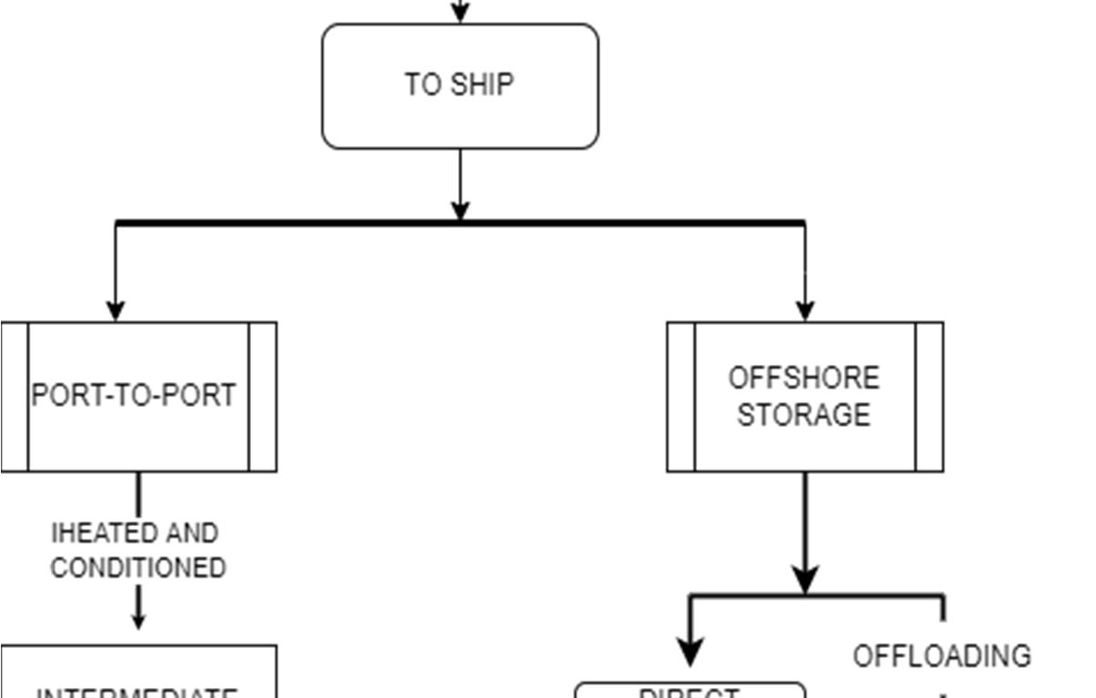
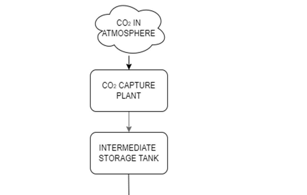
To make CO2 shipping economically feasible, a "clockwork" like relation is required between the source, components, ships, and the final sink. The general pathway of CO2 from the source (capturing plant) to sink is shown in the below flowchart (Fig. 3).
ISSN: 2321-9653; IC Value: 45.98; SJ Impact Factor: 7.538

Volume 11 Issue II Feb 2023- Available at www.ijraset.com
A. Dehydration
The CO2 captured from the atmosphere has to be dehydrated primarily. It assures the protection of the machinery involved. Though multiple researchers were conducted, erudite are not yet to conclude a consensus. They agree that the maximum allowable water content in the system must be between 10-50ppm. The apparatus and chemicals involved in this process are difficult to collect as the sellers tend to keep them confidential. Generally, molecular sieve dehydration or Triethylene glycol (TEG) unit is used. The presence of impurities such as NOx, SOx, amines, and glycols can turn out to be detrimental to this system. So they have to be removed before admitting it to the dehydration unit. Table 2. shows the list of impurities and their perceived effects on the dehydration unit.
Table 2 Common impurities and their effect on TEG and molecular sieve units on molecular sieve unit
B. Liquefaction
As explained earlier, liquefaction can be achieved by an open or closed refrigeration cycle. In a closed refrigeration cycle, external refrigerants such as ethane, propane, R134a, ammonia, or a combination of these are used. Generally, an open cycle is preferred when a large quantity of CO2 is considered [13]. Depending upon the target pressure and temperature condition, the selection of refrigerant is done. Table 3 shows the pressure each refrigerant ought to achieve.
Table 3
Despite the use of different refrigeration cycles and refrigerants, all the processes try to constrain CO2 at conditions at or near triple point because of its ease of transport, high density, and low storage costs. According to Nam [7], the process becomes most energy efficient at 6MPa and 295K.
The location of the liquefaction plant is also scrutinized. Nam et. Al. [7] has developed a modelling tool that suggests that the plant should be situated in high-emitting regions and can be connected to low-emitting regions via pipelines.
C. Storage
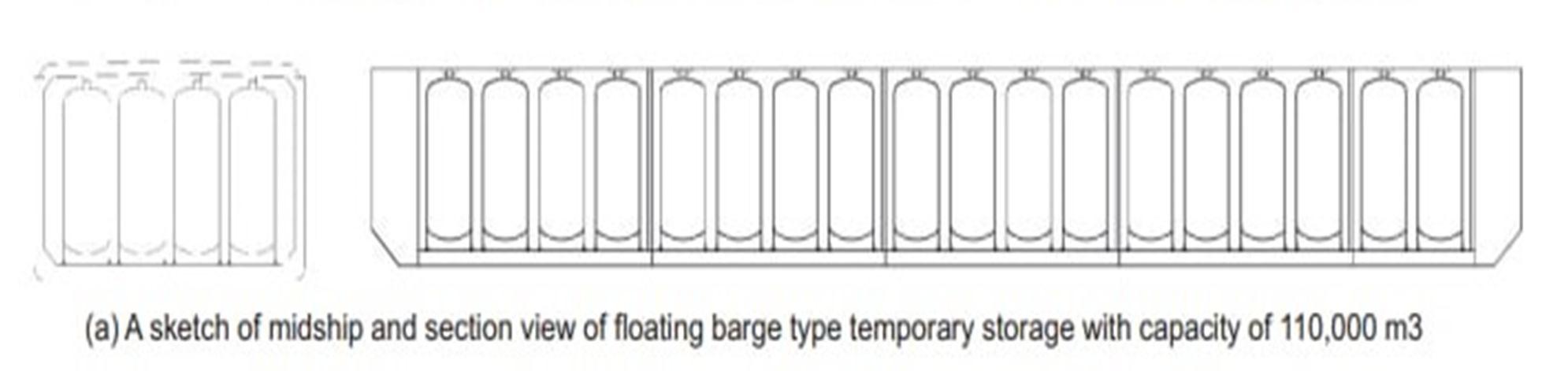
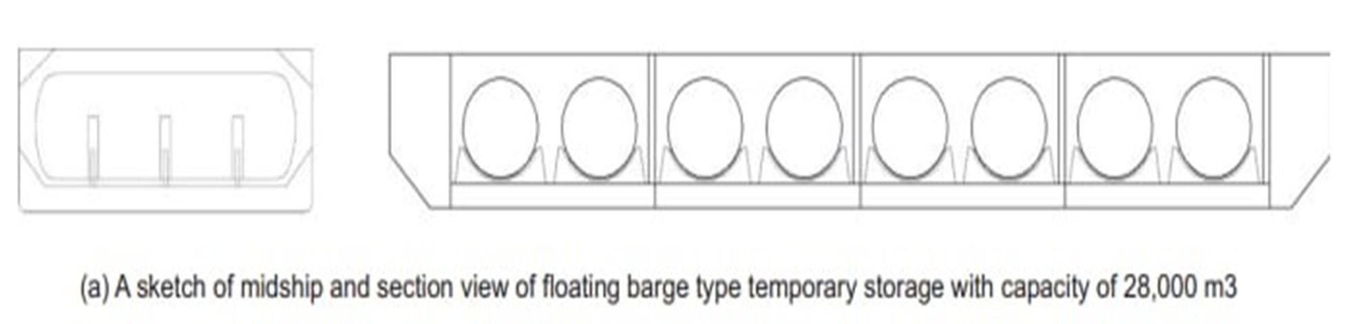
The liquefied gas has to be stored in an intermediate storage tank before being loaded into a ship. CO2 is stored in a bubble point. The tank is filled 72% - 98%, such that at any point CO2 in the tank exists as a mixture of gas and liquid. This resolves issues caused by pressure spikes or ingress of heat. The size of the storage tank must be at least 1.5 times the size of the vessel. Tanks can be built in bi-lobate, spherical and cylindrical shapes – a spherical shape is preferred as it is the cheaper option. The thickness of walls depends on the pressure it is intended to be used. Literature suggests carbon steel for spherical tanks and 9% Ni steel for cylindrical tanks. More research ought to happen in the case of intermediate tanks - it is not just the economic factors we have to consider. A failure can result in the sudden expulsion of a large quantity of CO2 into the atmosphere. This is detrimental to both the local ecosystem and humans alike. In case of non-availability of land onshore, one can install tanks in floating barges.
ISSN: 2321-9653; IC Value: 45.98; SJ Impact Factor: 7.538
Volume 11 Issue II Feb 2023- Available at www.ijraset.com
Floating Logistics Terminals (FLT) is an innovative method that can be of use. Currently, they are used to store LNG. These are cost-effective and easy to install (Fig. 4)
D. Loading
Loading of CO2 from intermediate tankers to ships can be done using mechanical arms or special hoses used for loading cryogenic liquids. Mechanical arms are preferred as they fail less frequently compared to hoses. Cargo is loaded using high-pressure, lowtemperature pumps. It is suggested to fill the CO2 in pressurized gas form and not liquid as this will hinder the formation of dry ice. To deter the build-up of pressure inside the vessel, CO2 vapors have to be removed using a return line, connected parallelly to the supply line. The loading time can be reduced by increasing the flow rate of CO2 - this helps to improve the economic characteristics of the process. While the option seems acceptable, it must be accompanied by an emergency release system to facilitate unplanned disconnection of the ship (due to emergencies like fire or rough weather) failure in the loading arm
E. Offloading
After the voyage, CO2 can be unloaded at its destination. It can either be an offshore site - which is deemed as the final destination or it can be an onshore site, which can be treated as a regular port-to-port transit. In the latter scenario, offloading and transferring it to the designated site is done via pipelines.
The technology for the process is already developed and is widely used in the food and ammonia industries. The types of machinery in use for the system share similarities with the one used in offloading other gaseous cargo such as LNG and LPG. But offloading at offshore sites throws a challenge as the technology is not yet developed. The selection of machinery for the process is expected to have an impact on vessel design. An advisable model is building an auxiliary platform, similar to intermediate storage. The platform serves as the base for several equipment and as a site for temporary storage. Though this comes at a higher CAPEX, it will ensure a continuous discharge, regardless of the condition of the weather. It will also reduce the time for offloading by5 times (it will take up to 50 hours in the absence of temporary offshore storage). Perchance availability of space occurs, and the very same FPSO can be used to install the temporary storage platform.
F. Injection System
Another model is the direct injection system, where cargo is discharged to a riser buoy. In such a system, the CO2 in the vessel has to be heated to 273K to prevent hydrate formation [14], pressurized to ~30MPa, and conditioned before injection within the vessel. The use of seawater for heating can be followed, but weather variations may affect the process. So, it is advised to have a system that makes use of waste heat for the process. The ship’s engine can give the energy for injection. The injection process must be continued throughout, as sudden cessations can result in the formation of dry ice.
ISSN: 2321-9653; IC Value: 45.98; SJ Impact Factor: 7.538
Volume 11 Issue II Feb 2023- Available at www.ijraset.com
V. A COMPARATIVE STUDY BETWEEN SHIPS, ROADS, RAILWAYS, AND PIPELINES FOR THE TRANSPORTATION OF CO2
CO2 transportation includes gaseous transport, liquid transport, dense-phase transport, supercritical transport, and solid transport. All except the last one is acceptable for long-distance, large-scale transportation [15].
A. Pipelines
CO2 lines are considered the best option for transporting a large amount of CO2 over a short distance (250km). The main deterring factor is the high initial investment and limited adaptability. Transportation cost for CO2 transport using pipelines is low.Phase transportation is very critical since temperature, pressure, and impurities have a great impact. Pipeline transportation ensures a continuous flow (i.e., it is a steady flow from source to sink) while other modes require intermediate storage sites [16]. To ensure a continuous flow, compressed gas is fed to the pipeline system – which increases the expenditure as distance increases. In order to maintain the supercritical phase throughout the line, a pump-based system is recommended for regulating the pressure. CO2 is compressed and recompressed at specific points in the pipelines – just like an amplifier in an electric circuit – which increases its energy consumption. The terrain through which the pipelines traverse also causes variation in pressure. Other arguments against the model are
1) that the construction of the pipeline and other supporting facilities can cause damage to the local environment
2) underground pipeline leaks can be detrimental to soil and underground water bodies.
3) Cause depletion of oxygen level
4) Harmful to aquatic organisms
B. Roads
Roads are a flexible and reliable method of small-scale CO2 transportation. An average truck can transport 18 tonnes of liquid CO2 [17]. For an economic operation, the distance between the source and sink must be below 320km. To maintain temperature and reduce evaporative loss, the container needs to be well insulated. Trucks find their applications in transporting CO2 for loading in ships and to reach areas where pipelines and ships cannot.
C. Railways
Rail cars are used for point-to-point transfer and could be used as potential temporary transport solutions on CCUS projects until additional transport options such as pipelines or high-capacity transport ships are developed. Operating expenses are associated with shipping and labor for loading and unloading rail cars.[18]. It is a cheaper option than the road. These types of transport systems do not get affected by weather or traffic conditionsBoth the source and the sink sites have to be near the rail line. Railway Transport is not asflexible as shipping or truck. It also doesn’t provide a continuous supply.
D. Ships
CO2 transport with the ship is the best method to transport CO2 from the source to near the coast and offshore storage site. They offer greater flexibility than pipelines. From various economic studies, it is made clear that for longer distances (>1000 km), ships are most suited. Shipping can be used in countries where the implementation of pipelines is not possible due to the possibility of natural calamities [19].
VI. ENVIRONMENTAL ASSESSMENT
A. Shipping Emissions And Control Measures
The emissions from the several types of machinery onboard a ship including the main engine, boilers, and incinerators contain up to 450 different compounds - whose detrimental effects reach out to global levels. The use of residual fuels (e.g., HFO) in shipping owing to its low cost takes up the blame for increasing air pollution significantly [20]. he effect of these activities within a range of 400km from the nearest land causes severe deterioration of the local environment [21]. On a related note, an intriguing yet concerning study unveiled the influence of aerosols generated from the ship engine exhaust on storm intensification and increased lightning in the north-eastern Indian Ocean and the South China Sea [22]. With the raising concerns, IMO has heightened its focus on curbing emissions. In 2008, IMO initiated two new actions to address emissions from ships -the Ship Energy Efficiency Management Plan (SEEMP) and the Energy Efficiency Design Index (EEDI). Under it, the following parameters are checked and suggestions were put forth:
ISSN: 2321-9653; IC Value: 45.98; SJ Impact Factor: 7.538
Volume 11 Issue II Feb 2023- Available at www.ijraset.com
1) Alternative fuels: Heavy Fuel Oil - has very high life cycle emissions, but is still considered favorable for shipping. Switching to alternative fuels will result in the reduction of carbon emissions [23]. Some of the challenges concerning this are the availability of bunkering infrastructure and the engine modifications needed [24]. Liquified natural gas is a promising alternative with its negligible sulphur content and high hydrogen to carbon ratio than diesel fuels. It has 20 to 30% lower CO2 emissions [25]. There are about 251 LNG-propelled vessels in operation worldwide as of 1 January 2020. Biofuels are another genre of alternatives. These are classified as first-generation biofuels such as hydrotreated vegetable oil (HVO), straight vegetable oil (SVO), fatty acid methyl ester (FAME), etc., and second-generation biofuels such as pyrolysis oil, lignocellulosic ethanol (LC Ethanol, Fischer- Tropsch diesel (FT-Diesel), etc.
B. Energy Efficiency
The EEDI is employed to reduce fuel consumption and increase energy efficiency by making necessary changes in the design of the ship’s propulsion systems, hull design, design speed, etc.
1) Concept And Speed: The ships’ energy efficiency is heavily dependent on their size, speed, and design of the beam and draught. With modern construction and maintenance, it is possible to extend the lifetime of ships to more than 30 years. Thus, retrofitting capabilities must be addressed at the design stage itself to ensure flexibility in operations. Although reduced speeds result in lesser emissions, the global uptake of speed reduction may be impractical as it may require regulations to be made which might be counterintuitive and hard to enforce.
2) Hull Design: By optimizing the hull design, hull resistance can be reduced and the propulsive efficiency improved. Hull design can be optimized by increasing the vessel size, changing hull shapes, hull coating, using resistance reduction devices, and lubrication.
3) Power And Propulsion Systems: Energy efficiency in propulsion engines can be improved by upgrading old engines, replacing them, and using exhaust gas heat recovery systems such as steam or electricity generation systems, etc.
4) Fleet Management, Logistics, And Incentives: By using the right kind of ship according to the size of the cargo, distance to be covered, and nature of the cargo, the efficiency of the shipping chain can be improved as a whole. Indeed, it will lead to improved energy efficiency. Also, carefully planned voyages, reduced wait times, and quicker turnaround times in port can lead to significant energy savings.
5) Voyage Optimization: By considering various factors such as weather, current, wave data, etc. It is possible to find the best route possible between the source and sink to optimize the voyage. This optimization helps to reduce fuel consumption and emissions.
6) Energy Management: Energy management is essential to restrict onboard energy consumption. Energy is required for propulsion, auxiliary operations, and sustenance of the crew.to reduce energy consumption, proper maintenance work should be carried out on all systems to ensure that maximum efficiency is achieved.
C. Renewable Energy Sources
Renewable energy can be generated on board ships or onshore to power ships while at berth (also called cold ironing). For instance, annual emissions can be reduced in the range of 5-10% by extracting wind power in various ways such as kites, sails, and Flettnertype rotor sails. Fuel cells can be used to shoulder a part of the energy supplied by generators.
D. Using CCUS Onboard Ship
The gaseous CO2 in exhaust gases can be captured using various technologies such as the use of membranes, absorption processes, and solvents [26]. But the current CCUS methods used on shore cannot be used onboard due to the increase in power consumption and large footprint.
VII. CHALLENGES AHEAD
This session discusses the broad range of challenges that have to be overcome to transform CCUS into a reality. It mainly deals with technical challenges but also discusses economical and legislative barricades briefly.
A. Economic challenges
The source of CO2 emission varies widely - ranging from a normal household to a multi-billion corporate industry. With changing sources, the condition of CO2 streams will also change. Hence a decentralized, dynamic approach should be taken, which makes the process arduous.
ISSN: 2321-9653; IC Value: 45.98; SJ Impact Factor: 7.538
Volume 11 Issue II Feb 2023- Available at www.ijraset.com
CCUS is considered an economic uncertainty because of the large CAPEX and OPEX as well as the financial uncertainty it throws in front. The land resources that are to be dedicated to the complex infrastructure to contain the cargo will take up valuable space, and that too will be taken from locations near ports.
Captured CO2 is often undervalued. As per Paris Agreement, the average global CO2 price must range between $40-$80 /t by 2020. Treating captured CO2 as a global commodity and lifting the sanctions will help to reduce the financial burden.
B. Legislative Challenges
Conventional norms tend to see CO2 as a waste/ by-product that threatens the integrity of life on earth rather than a viable commodity of commercial value. Several international conventions have promulgated legal frameworks that impede the development of CCUS.
The London protocol (1996) regards CO2 as a harmful waste and "prevents export of wastes to other countries for dumping"(A 2019 regulation strives to make amendments to this, thus providing hope for the future of CCUS). Several regional laws (centered in Europe) such as the CCS directive and ETS directive also strive to control CCUS activities. The former addresses only pipelines and is irrelevant to the study. The latter promotes only CO2 transmitted by pipelines, essentially handicapping the CCUS. Several national laws are also formed based on these. Norwegian National Law enforces the ETS scheme, hence barricading the implementation of shipping in CCUS.
C. Selection Of Materials
The selection of materials primarily depends on two criteria - temperature and dehydration. Carbon steel can be used when a low water level is present in the stream, but stainless steel is preferred when the water content is more (to prevent corrosion). The system can also be manufactured with alternating materials when additional components that help dehydration (like coolers, and scrubbers) are fitted in the line. It must be noted that the presence of impurities will continue to have its effects on the equipment (for instance, the presence of H2S cause the formation of a thin layer of iron sulfide which coats inside the pipeline and reduces the heat transfer). The operational temperature range of the system also significantly influences the selection of materials. Generally, the activities happen between 223K - 261K. Carbon steel treated for low-temperature and high-temperature operation can suffice the requirement. The use of 5% Ni steel and stainless-steel alloys can increase the cost of the project to such a level that it can even render the entire operation economically infeasible.
The use of non-metallic polymers is also explored [27]. PTFE, EPDM, and FKM are suitable for liquid CO2 environments. The use of polymers as seals for the equipment is also studied. Materials such as chloroprene, polyethylene, and Fluro-elastomers show cracking under depressurization. The lack of research on the behavior of seals at the triple point of CO2 makes further studies in accordance with the operation of CCUS obscure.
D. Boil-Off Gas Regeneration
The motion of the vessel and heat ingress cause boil-off gas (BOG) generation. A boil-off rate of 012%-0.15% is acceptable. The reliquefaction BOG is done by external refrigeration (Brayton cycle). The reliquefication process is similar to that used in LNG tankers.
E. Countering Hydrate Formation
The presence of water can lead to the formation of hydrates - which will cause slag formation and corrosion, on solvation with CO2 H2 increases the liquefaction pressure of the mixture - which means it will cause water to evaporate on depressurization and bond with gaseous CO2, which will accelerate the hydrate formations. In case of leakages, the interaction of CO2 causes hydrate formation and pH change.
F. Safety
The scientific, as well as legislative communities, were keen on safety considerations for both humans as well as the ecosystem as a whole. UK's health and safety executive issued an analysis of the dangers of CO2 systems, with CCUS in particular. Technical faults such as (the formation of dry ice, failure of loading arms, etc.) have to be dealt with. Grounding or sinking of ships is a major concern, as it is capable of releasing the entire CO2 in bulk. Due to the lack of available models and commercial implementation, the devastation of such a tragedy cannot be known, but the results will be unprecedented.
ISSN: 2321-9653; IC Value: 45.98; SJ Impact Factor: 7.538
Volume 11 Issue II Feb 2023- Available at www.ijraset.com
Though most of the technologies used resonates with those used in handling LNP/LPG, a great advantage of CO2 is that it is not explosive. Considerations of the impurities present should also be made. Studies have suggested that the unloading system and the intermediate storage tanks present the highest risk. Developing an emergency shutdown device (ESD), particularly for CCUS operation can mitigate the risk [28]. ESDs will shut off the transmission of CO2 during loading or unloading operations. An ESD contains fast-acting valves, loading arms with emergency release systems, and alarms.
G. Boiling Liquid Expanding Vapor Explosion (BLEVE)
The cracks or leaks in storage tanks or vessels can cause large expansion rates of gases [29]. The risk of BLEVE in low-pressure vessels (0.7 MPa, 223K) is considerably low compared to medium (I.5 MPa, 248K) and high-pressure vessels (4.5 MPa, 283K). Due to the non-flammability of CO2, subsequent ignition and BOG formation are prevented. Thus, the BLEVE is referred to as BLEVE.
VIII. CURRENT CCUS FACILITIES AROUND THE GLOBE
CCUS has been implemented in USA and Canada from as early as the 1960s for carbon dioxide-enhanced oil recovery (EOR) (Fig. 5). The world’s first large-scale CO2-EOR facility, Scurry Area Canyon Reef Operating Committee (SACROC), came into existence on January 26, 1972, in Texas, USA. Between 1972 and 2009, the SACROC project captured and injected more than 175 million tonnes of natural CO2.[30]
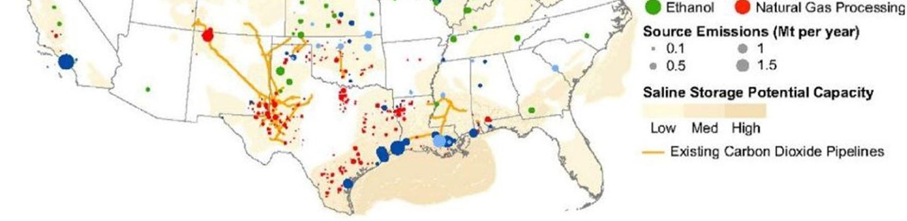
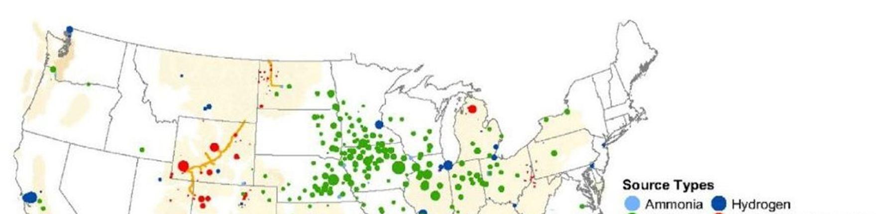
Though many such projects have been in operation for decades, all these employed pipelines or road transport as a means of transportation. This is largely attributed to the lack of ships capable of carrying CO2 in bulk, to make it economical. As of 2018, only four ships are currently employed for transporting CO2 from ammonia plants in northern Europe to coastal distribution terminals - which are used in food and beverage industries.[31]
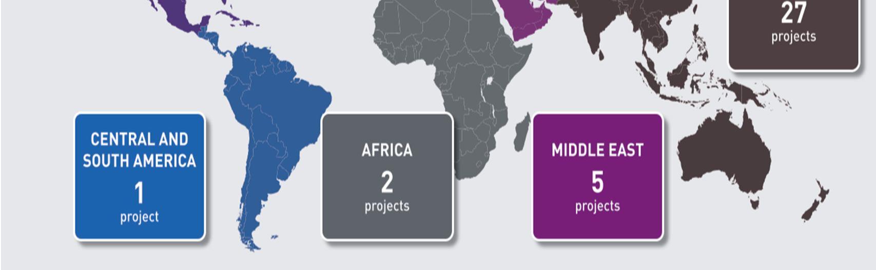
The recent development where Japanese, Korean, and Chinese ventures focussing on ship-based transportation of CO2 marks the beginning of a new era for the implementation of shipping in CCUS. The involvement of Korea and Japan paves an alternative path for countries that are geographically located far away from the sinks. For them, using pipelines is economically not feasible. Japanese shipping company NYK and Norwegian Knutsen Group have established a joint venture company or developing a liquified CO2 marine transportation and storage business. Near the end of 2021, Japanese shipping firm MOL and Mitsubishi Shipbuilding Co. announced the completion of a study on multiple hull forms for a liquified CO2 carrier.
Also, the world’s largest Shipbuilder Hyundai Heavy Industries (HHI), and Korea Shipbuilding and Offshore Engineering Co. (KSOE) together unveiled a design for a new 40,000 cubic-meter liquified CO2 Carrier in early 2021[32]. Figure 6 shows the current and proposed CCUS facilities globally.
ISSN: 2321-9653; IC Value: 45.98; SJ Impact Factor: 7.538
Volume 11 Issue II Feb 2023- Available at www.ijraset.com
IX. DISCUSSIONS AND CONCLUSIONS
With pressure mounting to bring down GHG in the atmosphere, it is high time that each company should start to introspect, either individually or with their components in the supply chain or with their counterparts in the market, and present an amicable stratagem to bring down their emission in accordance with the limits set by respective agencies. The seriousness of the problem is comprehendible when banks start to take an organization's climate impact into account before providing them loans. Similarly, constraints from governments, which appear in the form of laws, sanctions, or even non-cooperation will chock both small and large businesses. While the leviathans can afford to allocate capital for R&D in cutting down their emissions, smaller businesses can invest a sum in CCUS companies. This allows them to spend their capital in accordance with their emission. Inadvertently, this also preaches corporates to take up more responsibility for their actions and consider their social obligations while planning. Utilization of captured carbon can highly boost the sector. Limited utilization of carbon causes a sense of uncertainty and decreases the investments flowing to the field.
Despite numerous technological gaps, the literature suggests that using LCO2 carriers is one of the most favorable means of removing CO2 from the atmosphere. It is cheaper than long-distance pipeline projects, has flexibility between source and sink, and presents less threat of accidents. It also allows to induct the development in one particular subsystem in the chain – for instance, the capacity of the carbon capturing facility can be improved independently of the ship’s or cargo loading equipment’s capacity, which is not possible in the case of pipelines. The major impediments in the way are the legal framework and operational challenges. Due to the lack of working projects, flawless data collection is challenged. Above all, capital expenditure is an indispensable factor that governs projects. Proper integration of different systems in the CCS chain and their active coordination is demanded for an economically profitable operation. Rightly addressing the challenges and developing a legal framework to bolster the projects is instrumental in reducing the global CO2 content in the atmosphere.
References
[1] Knoope, M. M. J., A. Ramírez, and A. P. C. Faaij. Investing in CO2 transport infrastructure under uncertainty: A comparison between ships and pipelines. International journal of greenhouse gas control 41, 2015: pp. 174-193..
[2] Datta, Aparajita, Rafael De Leon, and Ramanan Krishnamoorti. Advancing carbon management through the global commoditization of CO2: the case for dualuse LNG-CO2 shipping. Carbon Management 11.6, 2020: pp. 611-630.
[3] Element Energy, TNO, Engineering Brevik, SINTEF, Polarkonsult. Shipping UK Cost Estimation Study; 2018.

[4] Morbee J, Serpa J, Tzimas E. Optimal planning of CO2 transmission infrastructure: The JRC InfraCCS tool. Energy Procedia, 2011;4: pp. 2772–7.
[5] Convery, Frank J. Origins and development of the EU ETS. Environmental and Resource Economics 43.3, 2009: pp. 391-412.

