
4 minute read
International Journal for Research in Applied Science & Engineering Technology (IJRASET)


ISSN: 2321-9653; IC Value: 45.98; SJ Impact Factor: 7.538
Volume 11 Issue III Mar 2023- Available at www.ijraset.com
Advertisement
1) Control Strategy
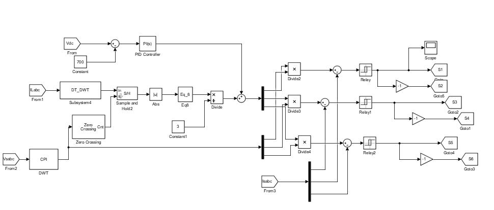
In this strategy, the estimated and sensed phase voltages of CPI are , supply currents ( , currents of load ( ), and the DC bus voltage of VSC ( ) are the control algorithm's feedback signals, these detected waves are processed in following order to the generate VSC gate pulses, are exposed in fig.2.
Here, peak magnitude of the voltages of CPI is determined as.
(1)
CPI voltage of the unit templates are intended as, (2)
A. Mathematical Calculation of the Average Active Power of the Load Currents ( )
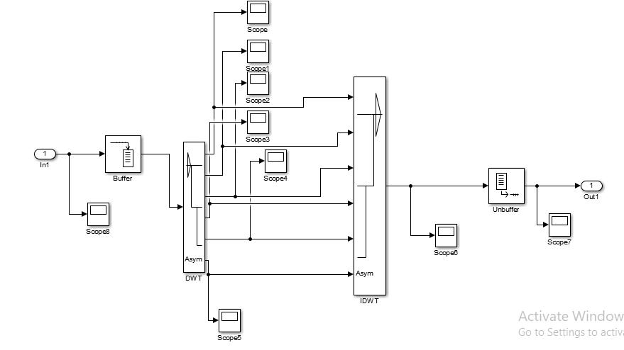
Measured Load currents ( ) are feedback signals of the control algorithm these detected signals are processed inorder shown in fig.2 to generate VSC gating pulses. Input signal sample down into 5 levels to get required band of frequencies by MRA. After sample down the input signal co-efficients are used for reconstruction by passing through low pass filters.
ISSN: 2321-9653; IC Value: 45.98; SJ Impact Factor: 7.538
Volume 11 Issue III Mar 2023- Available at www.ijraset.com
The fundamental load current retrieved with the co-efficients of each phase is in the quadrature to detected the load current of that phase with no delay. As a result, components ( ) of the predicted quadrature fundamental load currents are utilized to calculate the corresponding active power components ( ) respectively. The absolute (abs) magnitude of corresponding estimated quadrature components at each zero crossing of the related to each phase templates is used to extract these active power components. This extraction process's mathematical formulation for phase 'b' load current is as follows:
Therefore the phase ‘b' voltage and the current be as follows:
Where is the fundamental load current and is the harmonics of the phase ‘b’ load current. The DWT algorithm extracts the phase ‘b’ fundamental load current of the quadrature ( ).
Where is active power component of fundamental load current of the ’b’ phase. Similarly active power components for all the three load phases are estimated. Load balancing is accomplished by distributing active power equally throughout the three phases of the supply. The average of the active power equation of load currents is as follows: (9)
B. Mathematical Calculation of the Active Power Component of the DC-link Voltage Control ( )
For managing the DC bus voltage of VSC utilized as the DSTATCOM, the controller based on proportional integral (PI) method is recommended. The PI controller's control equation in discrete domain is as follows: (10)
Whereas is PI controller output is proportional gain, is integral gain respectively and the is an error input forwarded to PI controller. This controller regulates the DC link voltage to 700V. The controller parameters have been defined in Appendix.
Approximate of the Active Power Component ( ) is calculated as, by adding active power component of average load current and DC link voltage. (11)
C. Mathematical calculation of Reference Currents
This active source current is utilized to calculate reference balanced source currents by multiplying them by CPI unit voltage templates, as shown below, (12)
Where , and are reference balanced supply currents for ‘R’ , ‘Y’ , ‘B’ phases respectively.
ISSN: 2321-9653; IC Value: 45.98; SJ Impact Factor: 7.538
Volume 11 Issue III Mar 2023- Available at www.ijraset.com
D. Generation of Switching Pulses of VSC ( )
Measured source currents ( ) are calculate the inaccuracies, subtract the reference supply currents from the currents. These mistakes are fed into hysteresis current controller, which generates switching pulses for the DSTATCOM's VSC. By compensating currents, the generated VSC are added to source side in order to improve the THD and power factor correction across all load circumstances.
III.WAVELETTRANSFORMATION
The employment of a completely scaled modulated window in wavelet analysis eliminates the problem of signal clipping. It generates wavelets from a single basic wavelet with customizable resolution, translation, and scaling. This single basic wavelet is referred to as the mother wavelet. We acquire information and approximations via wavelet analysis. The details are the signal's lowscale, high-frequency components, whereas the approximations are the signal's high-scale, low-frequency components. The wavelet analysis's strength is its ability to represent signals in compact form and at multiple levels of resolution. Wavelet transforms are classified into two categories. They are discrete wavelets transform (DWT) and continuous wavelet transform (CWT) [6]. MRA can be done by construction and dilation in case of CWT whereas DWT; the MRA is performed in time-frequency plane by using filter banks.
The filter banks are used to analysis the signal by decomposing the original signal into different bands of frequency with equal width. The figure.4 shows a filter bank with two channels X (k) is the discrete time signal which is analysed by low pass L (z) and high pass H (z) with the help of filter banks. The filter bank output consists of equal number of samples similar to the input signal with half frequency content. By adding two outputs the output frequency and input frequency will be same but amount of data will be doubled. Hence down sampling is applied to output signal by a factor of ‘2’.
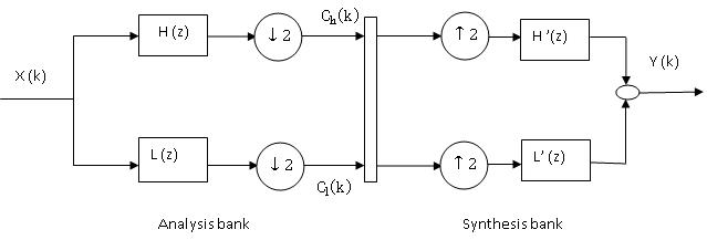
Figure.4. Estimation of fundamental by using decomposition and reconstruction
An equally efficient approach exists to implement the Inverse Discrete Wavelet Transforms (IDWT) through Synthesis filter bank is helpful to get the reconstructed signal. The signal will up be sampled by a factor of ‘2’ in synthesis filters bank and is given to low pass and the high pass filters. Here, output signal of two filters is added to get the reconstructed signal [7]
IV.SIMULATIONANDRESULTS
A MATLAB model based on this control algorithm is developed using Simulink and Sim Power toolboxes in a three-phase configuration for the control of a three-leg VSC-based DSTATCOM. Simulated results are presented for both balanced and unbalanced conditions under linear and nonlinear load respectively.
A. Without Dstatcom Case
The System Performance under Balanced Linear and Nonlinear Loads without dstatcom
The CPI voltages of a system are shown in Figure.5. Figure.6. shows the source current due to linear and nonlinear loads when the system is not connected to DSTATCOM. The compensating currents are not present in the system because DSTATCOM is not connected at CPI; due to this, the harmonics are present in the load and source currents. The source currents are not sinusoidal in this non-linear load condition. Figure.7 represents load currents due to non-linear load. Figure.8 represents load currents due to linear load conditions.
