6 minute read
Energy Management For Renewable Hybrid System Based OnArtificial Neural Networks (ANN)

from Energy Management For Renewable Hybrid System Based On Artificial Neural Networks (ANN)
by IJRASET

M. Nagendra Babu1 , P. Pavan
, K. Rama Mohan3 , G. Raja Rao4 , K. Srinivasa Rao5 , G. Tejaswi6
Advertisement
5UG Scholar Students, 6Associate Professor, Dept. of EEE, Sree Vahini Institute of Science & Technology, Tiruvuru, N.T.R Dist, A. P
Abstract: It has become necessary in recent years to use renewable energy sources, such as wind and solar energy, to meet the load demand. Because of their endless existence and environmentally friendly nature, they are useful for power generation. The management of energy in hybrid wind-solar power sources is the topic of this article. Using a common current source interface multiple-input DC-DC converter, the photovoltaic (PV) array, wind turbine, and battery storage are all connected. The power control between intermittent renewable energy generation, energy storage, and the grid is maintained by the artificial neural network (ANN) controller. For wind turbines to produce the most electricity, variable speed control can be used. For solar systems, the Maximum Power Point Tracking (MPPT) algorithm is used. By keeping the common DC voltage constant, the grid interface inverter sends the energy drawn from the PV array and wind turbine into the grid. Using MATLAB Simulink, the complete control strategy is subjected to a simulation study. The results of the simulation show the photovoltaic/wind hybrid system's dynamic behavior and control effectiveness.
Keywords: Renewable Energy, Solar energy, Photovoltaic array, Wind Energy, Hybrid system, Energy management, Artificial Neural Networks (ANN) Controller
I. INTRODUCTION
The energy that is obtained from resources that are found in nature, such as sunshine, wind, tides, waves, etc., is known as renewable energy. A hybrid generation system is used to provide enough electricity to fulfill the rising load demand. In a hybrid system, various renewable energy sources are integrated. The proposed system is a hybrid one that combines solar and wind power. Opportunities for using wind and solar resources for the creation of electric power have been made possible by advanced wind turbines and photovoltaic generating technology. They exhibit erratic, unpredictable conduct. Using both wind and solar energy effectively, the wind and solar integrated power supply system provides a fair source of energy. Multiple control techniques are employed in a hybrid energy system for efficient and smooth power transfer. The type of converter used in the system, which is connected between the energy supply and the loads, determines the microgrid configuration. In order to regulate the energy among various resources, a control algorithm is needed [1]. It is applied in a setting with real-time control. The stand-alone hybrid system is employed to provide power to remote places connected to a flimsy grid. Depending on the weather, a hybrid energy-generating system is employed to satisfy the power requirement. The battery, which consists of lead-acid batteries linked in a series or parallel array, is used to store energy. The overuse of power compromises system dependability by causing an overvoltage on the DC bus. The adaptive control approach is utilized to mitigate reliability and over-voltage problems during excessive generating [2]. By keeping an eye on the battery's level of charge and the dc bus voltage, it is archived (SOC). The processing and communication requirements are reduced by the energy management system-based multi-agent system (MAS). Middle-level and upper-level agents are its two agents [3]. The system is simple to maintain and regulate. The extraction of the load current and switching of the utility grid-side converter (UGC) is accomplished using an adaptive control technique based on least mean mixed norms (LMMN) [7]. It is used to lower the harmonic content of grid currents, enhancing the system's power quality. In the hybrid system, various controller types are employed. PID controllers are the ones that are most frequently utilized. In fractional-order power generation and energy storage systems, frequency deviation is controlled using a fractional-order proportional-integral-derivative (FOPID) controller [4]. The output response oscillations are decreased, and the transient response is improved using a PID controller. The frequency deviation's settling time is shortened using a PID controller [11]. By using the wind turbine to drive the permanent magnet synchronous generator (PMSG), a gearbox setup that needs routine maintenance is avoided.
ISSN: 2321-9653; IC Value: 45.98; SJ Impact Factor: 7.538


Volume 11 Issue IV Apr 2023- Available at www.ijraset.com
A hysteresis controller is part of the hybrid wind-driven PMSG-PV system. It has excellent efficiency and a high-power factor. In order to get the most power out of both sources, PV and PSMG work together to create the current command [9].
Both the PV system and the wind energy conversion system employ artificial neural networks. It helps renewable energy sources perform as well as possible. The input layer, the hidden layer, and the output layer are all parts of an ANN's architecture [12]. The MPPT controller uses an RBFN-based Radial Basis Function Network (RBFN) to track maximum power from both solar and wind energy systems [5]. The two MPPT algorithms are combined to create a single RFBN-based MPPT controller that has been updated. As a result, the system became less complicated. Other neuro-fuzzy models can't match the speed of the adaptive neuro-fuzzy inference system (ANFIS). The three-phase inverter is subject to ANFIS-based regulation in order to manage the output power sent to the grid. It features two controllers: an active power controller and a reactive power controller [6].
Due to the resistance of time and place, it is exceedingly challenging to utilize solar and wind energy in all weather conditions alone through a solar system or a wind system. In order to address this need, a system based on renewable resources is also required, and wind/solar hybrid systems with battery storage can do so. This paper's main goal is to integrate hybrid solar and wind renewable sources to meet load power demand. The Luo Converter is used to increase efficiency and obtain significant voltage gains [8]. Low voltage ripple is provided by a Luo converter combined with great power density. The system's power is managed via an Artificial Neural Network. It is steady and dependable. By utilizingANN, this system has low power and cost dissipation [10]. This paper is organized as follows. Section II introduces the proposed system Architecture and Modeling of Proposed architecture
In section III the artificial neural networks described. In section IV simulation and results Analysis of Proposed system. Finally, the summary of the proposed system is concluded in section V
II. PROPOSED SYSTEM ARCHITECTURE
Photovoltaic (PV) arrays, wind turbines, multiple input DC/DC converters, and PWM inverters make up the proposed Artificial Neural Network-based energy management for the hybrid renewable system. Fig 1 depicts the block diagram of the proposed ANN-controlled PV/wind hybrid generating system. Electricity is produced from solar energy by photovoltaic cells. Higher voltages, currents, and power levels are produced by connecting photovoltaic cells in series or parallel. Direct current is the current generated by the PV system (DC). When solar panels are utilized to generate power, there are no emissions that result in the greenhouse effect. Solar-generated electricity is crucial for the transition to the generation of clean energy. To track the maximum power generated by the PV system, MPPT technology is employed.
ISSN: 2321-9653; IC Value: 45.98; SJ Impact Factor: 7.538
Volume 11 Issue IV Apr 2023- Available at www.ijraset.com
The wind is utilized to produce current through the wind turbine generator (WTG). The kinetic energy is transformed into mechanical energy using a wind turbine. Electrical energy is created by a generator using mechanical energy. Wind turbines use alternating currents as their source of current. Wind turbine output is sent to a rectifier, which converts AC to DC. The multi-input DC-DC converter is supplied with energy from the wind and solar panels as input. As a DC-DC converter, the Luo converter is employed here. On the output side, it is used to step up the voltage. To increase the system's efficiency and achieve high voltage gain, a Luo converter is employed. A pulse-width modulation (PWM) inverter is used to convert the DC output of the Luo converter to AC. The inverter's PWM approach produces a constant output voltage regardless of the load. Without any dissipation, it regulates the amount of power given to the load.
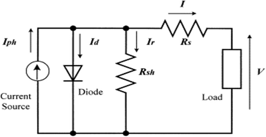
A. PV System Modelling
Fig. 2 depicts the PV cell's comparable circuit. A current source with a diode connected in parallel to it models a perfect solar cell. Nevertheless, no solar cell is perfect, so the model has series and shunt resistance incorporated, as seen in the picture. Rs is the very low value of the series resistance. The comparable shunt resistance, or Rp, has a very high value.
Applying Kirchhoff’s current law to the junction where ,diode, , = + + ……… (1)
We get the following equation for the PV cell current = ( + ) (2)
Where, is insolation current, I is the cell current, is the reverse saturation current, V is the cell voltage, is the series resistance, is the parallel resistance and is the thermal voltage.
B. MPPT
The MPPT algorithm is based on the computation of the PV power and the power change by sampling both the PV current and voltage in the Perturb and Observe (P&O) approach. The tracker works by regularly increasing or decreasing the voltage of the solar array. While using instantaneous PV array voltage and current, the technique functions as long as sampling takes place just once during each switching cycle.
Up until the MPP is reached, the procedure is periodically repeated. After that, the system oscillates about the MPP. By decreasing the perturbation step size, the oscillation can be decreased. The MPPT, however, is slower with a smaller perturbation size. The flowchart for the traditional P&O technique is shown in Fig. 3


