1 minute read
International Journal for Research in Applied Science & Engineering Technology (IJRASET)

from Design and Computational Analysis of the Conventional Vaned Diffuser for a Turbocharger Compressor
by IJRASET


ISSN: 2321-9653; IC Value: 45.98; SJ Impact Factor: 7.538
Advertisement
Volume 11 Issue I Jan 2023- Available at www.ijraset.com
III. NUMERICALPROCEDUREFORSTEADY STATESIMULATION
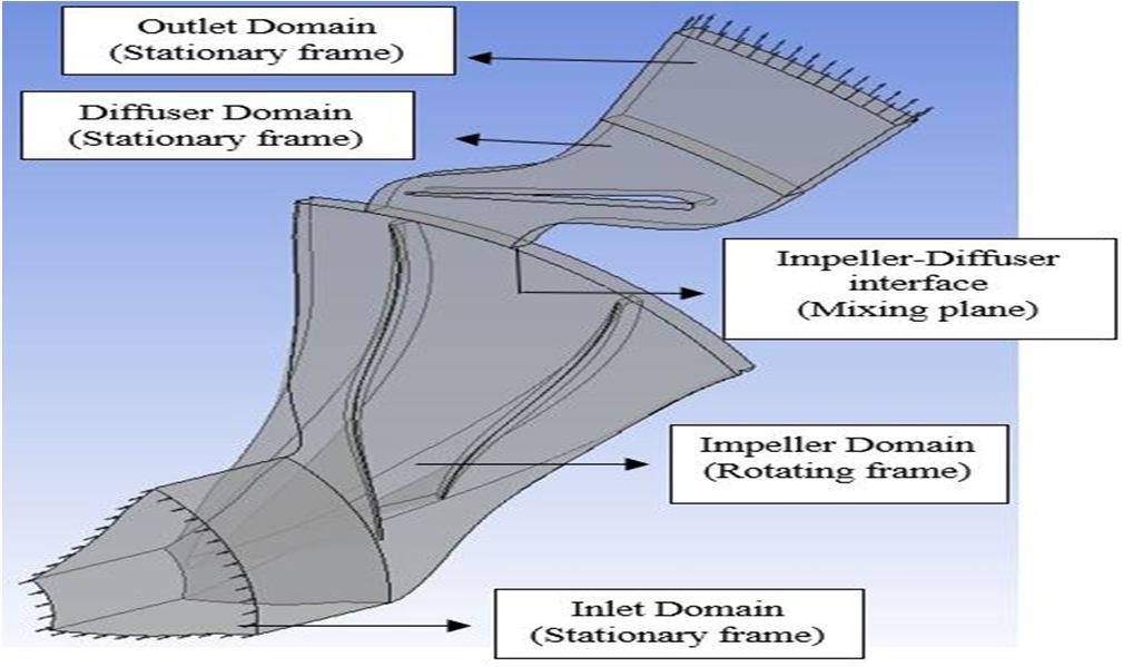
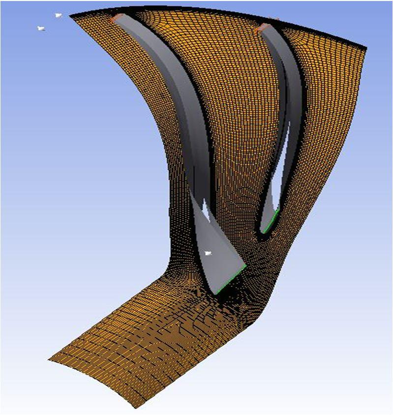
The investigation domain is decided to be from compressor inlet to Rmax station, which is shown in Fig. 1. The vaneless diffuser and the impeller are discretised as a single passage. The Turbo Grid mesh generator from ANSYS uses a structured multi-block meshing technique to achieve discretization. One block of "C" mesh and four blocks of H mesh make comprise the topology of the impeller and wedge diffuser meshes, which are frequently employed in turbomachinery applications. An "H" mesh topology is employed over the upstream, downstream, and adjacent blocks to the suction and pressure side of the "C" block in this case, while a "C" mesh block is formed around the vane. A block of "C" mesh and a block of H mesh are combined to form the impeller's tip clearance mesh. The stage's mesh quality is good, and the blade's leading and trailing edges have good orthogonality. y+ less than or equal to 2 is acquired at the walls in order to capture the viscous effects close to the compressor walls. After the mesh independence research, the entire compressor stage is typically built using roughly 24 lakhs of elements. The computerised grids are displayed in Fig.2

B. Boundary Conditions
Figure 3 depicts the model to be analysed in steady state module. Only one blade passage was used by defining rotational periodicity to the neighbouring wall. By doing this, it removes the need to analyse the entire compressor and cuts down on simulation time. 2% of the impeller tip radius was chosen as the impeller-diffuser interaction location [11]. Because the impeller shroud is fixed in the stationary frame, a counter rotating wall is forced on it. All inlet, impeller, and diffuser domain walls were given a no-slip state. While static pressure was employed as the exit boundary condition with an impeller tip mach number of 1:33, ambient total pressure and temperature were used as the inlet boundary conditions. In order to achieve performance, outlet static pressure was changed.


