
3 minute read
International Journal for Research in Applied Science & Engineering Technology (IJRASET)


ISSN: 2321-9653; IC Value: 45.98; SJ Impact Factor: 7.538
Volume 11 Issue III Mar 2023- Available at www.ijraset.com
Advertisement
Table 1 Comparison of properties between Al, Al A356 T6 and ABS plastic for basic model
Table 2 shows the components of drone that frame carries along with quantity and weight [11-14]. In current work, frame design is made to withstand a load of 2.14 kg (ie. 21N)
Table 2 Components of drone that frame carries along with quantity and weight the
B. Analysis of Basic Design of Quad Copter Frame
Quad copter frame is analyzed for static stress [15, 16] using Fusion 360 software for which the following materials are considered: Aluminium, A356 T6 and ABS plastic.
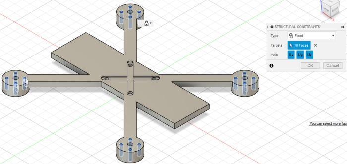
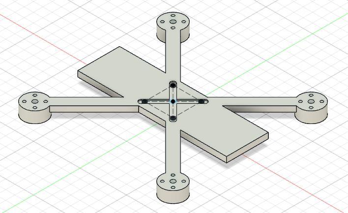
1) Boundary Conditions: The motor mount holes (4X4=16) are fixed (Fig 3)
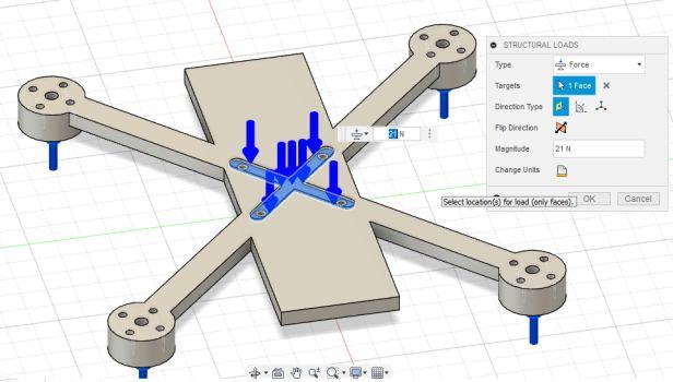
2) Loading Conditions: Weight of 21N is applied on the frame, along with thrust of 10N for each motor acting upwards. (Fig 4)
3) Mesh Settings: Fine mesh of tetrahedron shape of absolute size of 1mm is created with 760746 nodes and 518391 elements.
ISSN: 2321-9653; IC Value: 45.98; SJ Impact Factor: 7.538
Volume 11 Issue III Mar 2023- Available at www.ijraset.com
C. Comparative analysis of basic design of quad copter frame made of Al, A356T6, ABS plastic
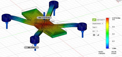
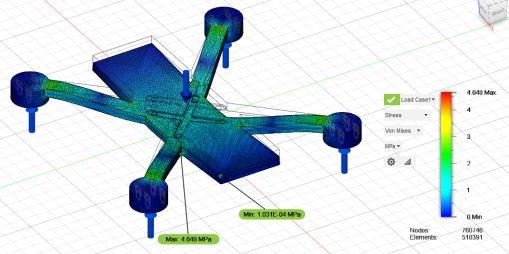
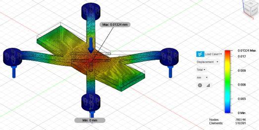
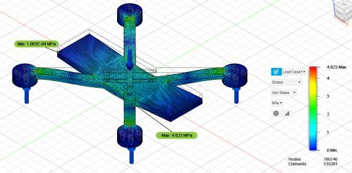

The Maximum displacement and Stress for Aluminium material is as shown as fig 5 and 6 respectively below.
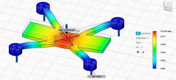
Stress and maximum displacement for Al A356 T6 is as shown in fig 7 and 8 respectively
Stress and maximum displacement for ABS is as shown in fig 9 and 10 respectively
The following table no 3 compares the static stress analysis results of all three materials used.
Table 3 Comparison of static stress analysis results for Al, Al A356 T6 and ABS plastic of basic model
The ultimate factor of safety (FOS) used in aircraft can be about 1.5. In general, an FOS of 2 is considered as a standard for tested structures and 3 for untested structures. The most important thing in aircraft application is it should have the lowest weight possible [2]. The FOS based on yield strength of materials is 15 for Al as well as Al A356 T6 whereas for ABS plastic it is 4.303. Amongst other factors, it is mainly weight that has its impact on the FOS and the least weight is with ABS plastic as it is only 39.26% of the weight of Al and 39.7% of the weight of Al A356 T6. So, ABS plastic is chosen for further analysis such that the strength is not compromise while further reducing the weight of the frame using shape optimization technique.
ISSN: 2321-9653; IC Value: 45.98; SJ Impact Factor: 7.538
Volume 11 Issue III Mar 2023- Available at www.ijraset.com
V. SHAPEOPTIMIZATIONANDSTRESSANALYSISOFQUADCOPTERFRAMEMADEOFABSPLASTIC
A. Shape Optimization of Quad Copter Frame (Iteration 1)
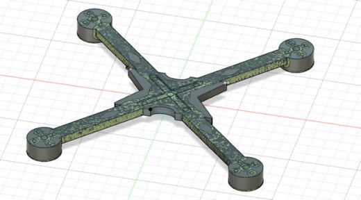
Fusion 360 software is used to shape optimize the basic model of quad copter frame designed to bring out the best of the design. The following is the 1st iteration of the design to cut down mass and material. The 1st iteration is the basic model of the quad copter frame on which the boundary conditions and loads are applied as discussed in section 4.2. Shape optimization or otherwise topology optimization is applied to find the regions in the design component that does not contribute much to load or otherwise whose absence does not affect the strength, stiffness or rigidity of the component [17 to 23].
B. Analysis of Shape Optimized Quad Copter Frame
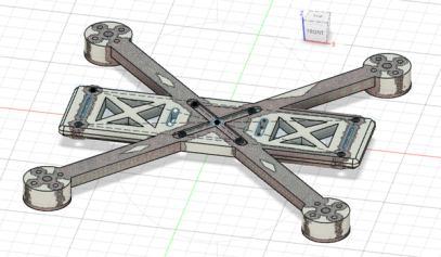
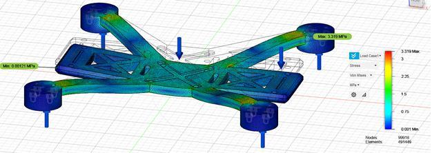
On simulating for optimizing shape of the basic model, the target is set to reduce mass by at least 30%. This is done by modifying the design in every iteration such that the design still meets the strength criteria. The 1st iteration is worked out on the basic model (fig 2), and the stress distribution is studied (Fig 11). The blue color region in fig. 11 shows that the region has negligible stress and that region is not contributing much in carrying the load and hence can be reduced. The basic model is redesigned keeping in mind the stress distribution and fig. 12 is the outcome whose weight came down to 76.75g.
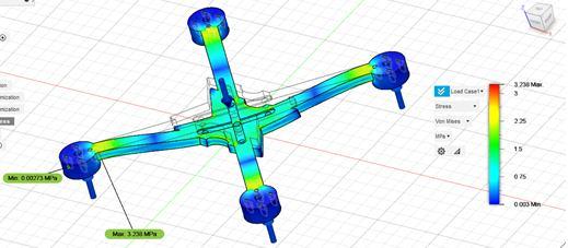
Fig 12 Iteration 2 a) shape optimized design b) stress analysis
On further applying shape optimization technique on fig. 12, fig. 13 is resulted. The weight of the final component is 54.54g with a 35% weight reduction. Lesser weight gives more flight time and payload capacity to the drone. The maximum stress in the final component after shape optimization is 3.238MPa and the minimum FOS is 6.39.
