
1 minute read
International Journal for Research in Applied Science & Engineering Technology (IJRASET)

from Design and Analysis of Microstrip Patch Antenna Arrays for UWB Applications at C-band
by IJRASET

ISSN: 2321-9653; IC Value: 45.98; SJ Impact Factor: 7.538
Volume 11 Issue II Feb 2023- Available at www.ijraset.com
Advertisement
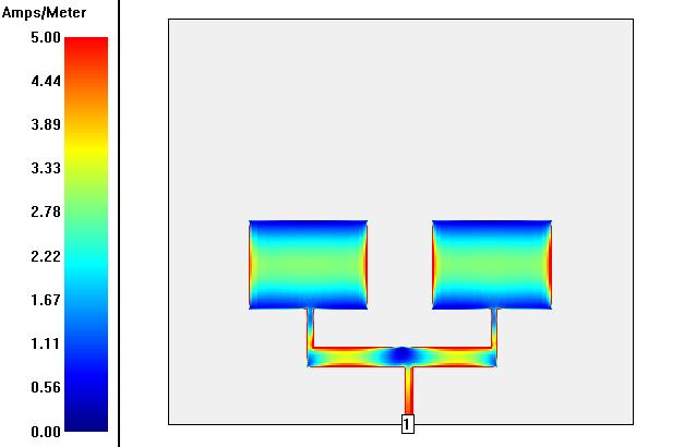
IV.CONCLUSIONS
A proposed microstrip patch antenna array at 4 - 4.5 GHz frequency with 50 ohms input impedance. The proposed antennas performance was improved in terms of thickness of the feed line and thickness of the substrate material. We used the same dimensions for all the antennas with different box sizes. The return loss increased as we increased the number of antennas in the array. The single rectangular microstrip patch antenna at 4.36 GHz with 50 ohms input impedance has a smooth return loss of12.14 dB but as we increased the number of antennas in the series, we get the high return loss but at different frequency. Designs of two element patch antennas and four elements patch antennas are presented in this paper. The overall simulation results proved that the proposed microstrip patch antenna array in terms of gain, size and bandwidth.


References
[1] S Constantine A. Balanis “Antenna Theory: Analysis and Design,” 3rd Edition, 2005 John Wiley and Sons, Inc. Hoboken, New Jersey.
[2] S Constantine A. Balanis ,Antenna Theory: Analysis and Design, 3rd Edition, John Wiley and Sons, Inc. Hoboken, New Jersey, 2005.
[3] NEWS Federal Communication Commission High Frequency releases, 2002.
[4] Seok H. Choi, Jong K. Park, Sun K. Kim, and Jae Y. Park, A new Ultra-Wideband Antenna for UWB Applications, MICROWAVE AND OPTICAL TECHNOLOGY LETTERS / Vol. 40, No. 5, March 5 2004.

