3 minute read
Design and Analysis of ANN Control based LLC Resonant Converter


Mr Aneerudh A Research Scholar, Dayananda Sagar College of Engineering Banglore ,Karnataka

Advertisement
Abstract: In this, artificial neural network controller is designed for LLC resonant converter for voltage regulation. The performance of the proposed converter with proportional-integral (PI) controller and ANN controller are analysed from the simulation results. A voltage mode control is provided to get regulated load voltage irrespective of the changes in supply. ANN controller is used for the voltage mode control and the efficiency of the proposed ANN controller is estimated and comparison is made with conventional PI controller. The simulation work is done with MATLAB/Simulink software.
Keywords: Dc-Dc Converters, Resonant converters, Voltage mode Control, PI controller, ANN.
I. INTRODUCTION
In past, the conventional energy sources such as coal, gas, oil, etc, are utilized for power generation until the renewable sources are introduced for electrical power generation. Also, the regulations regarding emission of pollutants and impact on environmental pollution reduction caused the quick growth on these renewable sources. The Photovoltaic (PV) energy was utilized for charging the batteries in isolated areas and wind turbines also used in few occasions. These two energy sources are extended over other applications also and they both get combined to design hybrid system after the idea of grid connected system is introduced. Several new ideas regarding control circuits, design of converters, MPPT (Maximum Power Point Tracking), real and reactive power control and injection, etc, are proposed regarding the hybrid energy resources. The key issue in this is the availability of irradiation in solar and wind speed cannot be predetermined as it relied on the environmental conditions. The wind and solar energies are complement to each other and provides power almost all over the year is the main reason for choosing them for hybrid power generation. Hence these two can be used as main power sources and also it is possible to include an auxiliary power source such as battery, diesel plant, biogas, fuel cell, etc, as backup As the power generation unit consists of multiple sources, it is more reliable than individual sources irrespective of the location of the power generation unit. It can be utilized in remote villages as the distribution of electrical energy from grid is near to impossible in those locations. A control strategy is important for the hybrid system in order to regulate the variables such as voltage, power, etc. As these renewable sources are volatile in nature voltage control is essential for the reliable power generation and distribution. Various renewable sources are interlinked using dc bus in which the voltage regulation is provided using controllers such as PI control (Proportional Integral), PID control (Proportional Integral Derivative), SM control (Sliding Mode Control), etc, in order to enhance the performance of the HRES. In this paper, a dc-dc converter system with LLC converter is added to proposed system for providing voltage regulation for dc load. The resonant LLC converter is designed for dc-dc conversion and a comparison is made with conventional controller and proposed controller under varying load conditions. A simple voltage mode control loop is designed with PI and ANN controller and the performance of the proposed system is observed for these two controllers based on simulation results A hardware prototype model was designed and both buck and boost operations are performed for the output voltage range of 4-20V with input voltage of 12V.
II. LLC CONVERTER
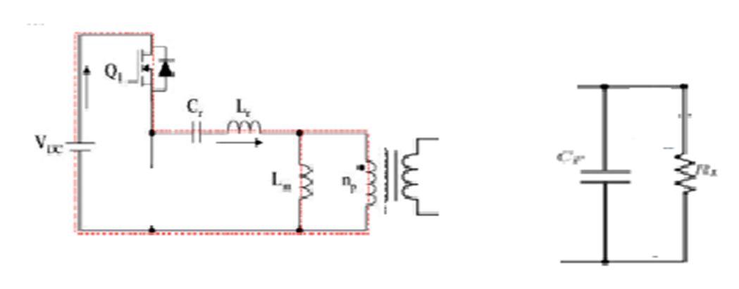
The proposed LLC converter is given in Fig 1 as follows:
ISSN: 2321-9653; IC Value: 45.98; SJ Impact Factor: 7.538
Volume 11 Issue II Feb 2023- Available at www.ijraset.com
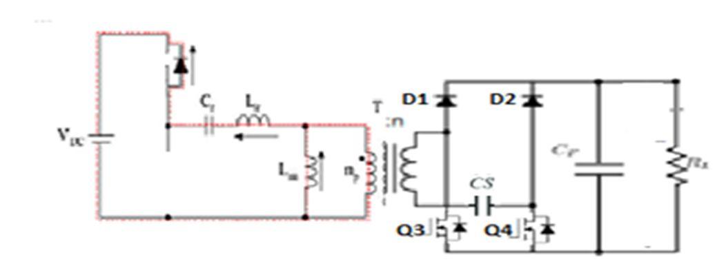
In this, when Q1 is ON, the inductor get charged and the capacitor get discharged and provides energy to the primary winding of transformer. In secondary, the energy is utilized by the load with the help of diode rectifier. When Q2 is ON, the inductor starts discharging and provides energy to transformer primary and resonant capacitor. In this also, the load utilizes the energy induced in secondary with the help of diode rectifier.
A. Mode 1
This mode is started at the instant, switch Q2 is off. The ILr current starts to flow in opposite direction through the body diode of Q1. This will cause the secondary side diode D1 to conduct and Io starts to increase. The magnetizing inductance of the coupled inductor Lm is getting charged with input source voltage.
B. Mode 2
In this, the Q1 is turned ON and the ILr current reaches positive. The secondary side diode D1 conducts and the secondary voltage is fixed to Vo. The magnetizing inductance Lm is linearly charged with load voltage, and hence the resonant circuit is not active during this time. When the currents ILr and ILm are equal, mode3 starts.
C. Mode 3
Mode 3 starts when the ILr and ILm are equal. The diodes D1 and D2 are reverse biased and the transformer secondary voltage is less than that of load voltage. When the MOSFET Q1 is turned off, this mode ends.
The next half cycle is same by turning Q2 ON and OFF. The procedure of designing the proposed converter is provided below:
The design of the proposed converter is done based on the rated input source voltage.
The load regulation is performed with zero loading conditions at maximum possible input source voltage.
1) Step 1: The turns ratio of transformer and voltage gain is provided below: