12 minute read
Based on a Novel Modular Converter, Modular Battery Management for SRM drives in Hybrid Vehicles

from Based on a Novel Modular Converter, Modular Battery Management for SRM drives in Hybrid Vehicles
by IJRASET

Dr. j.
Ganesh Prasad
Advertisement
Reddy1, G. Nandini2, G. Theja Sri3 , G. Hareesh4 , G. Sai Kumar5 , D Rassol6
1Professor, Department of EEE, Sree Vahini Institute of Science and Technology, Tiruvuru, NTR District, AP, India 2, 3, 4, 5, 6UG Scholor Students, Sree Vahini Institute of Science and Technology, Tiruvuru, NTR District, AP, India

Abstract: In order to address environmental issues, the automotive industry is moving in a significant direction towards hybrid vehicles. One of its primary drive system options is a switching reluctance motor (SRM). This article designs a brand-new SRM converter topology. The innovative converter can manage battery energy and implement multi-level control. The battery control circuit is created in a modular manner, allowing the number of battery modules (BMs) to be chosen based on system needs. A hybrid vehicle's driving conditions are used to separate the converter's status into five states and conduct detailed analyses of each. Ultimately, the novel converter's simulation model and testing platform are constructed. The findings of the simulation and experiment confirm the viability of various working modes of the system's fault tolerance and reliability have been considerably enhanced by the innovative converter topology and the ability to individually regulate each BM.
Index Terms: Battery energy management, hybrid electric vehicle, novel converter, switched reluctance motor (SRM)
I. INTRODUCTION
Grown and as people's living standards have improved. The popularity of automobiles not only makes Automobiles have become a necessity for the majority of families as the automobile industry has life more convenient for individuals, but it also inexorably poses problems for the environment and energy systems on a worldwide scale [1-3]. There is a shortage of resources in the world because petroleum, the primary energy source for vehicles that burn oil, is not renewable. Carbon monoxide, hydrocarbons, nitrogen oxides, sulphur dioxide, lead compounds, and solid particles are the principal pollutants in the exhaust of oil-burning automobiles. These pollutants cause acid rain, the greenhouse effect, and other severe atmospheric environmental issues. One of the key strategies for resolving this issue efficiently is to use new energy electric automobiles. Electric vehicles use electric motors, battery management systems, motor drive control systems, and other devices to replace the combustion engines in fuel vehicles [4-5]. Electric vehicles combine vehicle engineering technology with electrical engineering technology, control engineering technology, and other technologies. in comparison to it is possible to significantly lower the energy use of conventional vehicles and the emissions of pollutants like carbon dioxide.
Pure electric vehicles, fuel cell vehicles, and hybrid vehicles represent the three main development and application axes for electric vehicles. Pure electric vehicles cannot be utilised extensively in the near future due to their limited battery capacity, inadequate charging stations, and poor endurance. Also, hydrogen fuel cells are the primary fuel source for fuel cell automobiles. Using hydrogen energy can successfully address the issues of resource scarcity and reduced environmental pollution. The industrialisation process is currently gradual, however, due to limitations imposed by the advancement of on-board hydrogen storage technology, fuel cell technology, and hydrogen station infrastructure. Hybrid vehicles not only have greater endurance capacity but also efficiently reduce the amount of environmental pollution produced by fuel-powered vehicles. This feature makes hybrid vehicles more appealing to drivers who are accustomed to operating fuel-powered vehicles. It is currently one of the main application directions of electric vehicles [6-9].
The following are the general specifications for motors in hybrid vehicles: straightforward structure, affordable price, good ruggedness, and high efficiency. The speed regulation for DC motors is straightforward, and the technology is advanced [10]. However, the existing application has steadily been scaled back due to its low dependability and efficiency. An induction motor has several advantages over a dc motor, including a simple, robust structure, high efficiency, and low cost. However, the disadvantages of low starting torque and large starting current have a significant impact on the hybrid vehicle system, which requires frequent starts and stops [11].
ISSN: 2321-9653; IC Value: 45.98; SJ Impact Factor: 7.538
Volume 11 Issue III Mar 2023- Available at www.ijraset.com
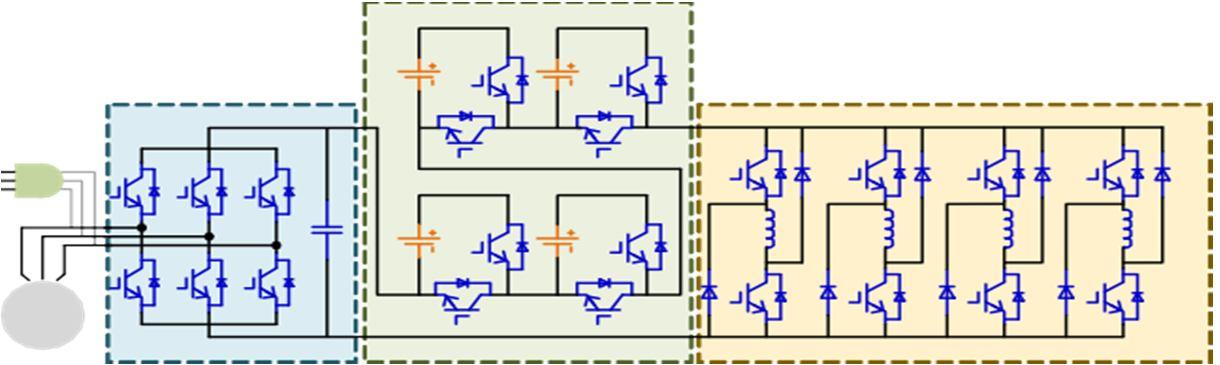
The hybrid vehicle system based on SRM is depicted in Figure 1. E is the system's engine, which can operate either independently or in tandem with the SRM. G stands for the generator, which When the engine has extra power, it is driven to recharge the battery. The topology of BM, a battery module made up of a battery cell and a half-bridge, is depicted in Figure 2. Four BMs are used in this paper's examination as examples.
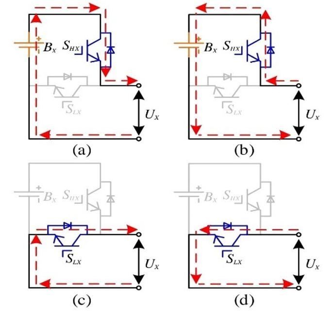
The battery pack made up of k BMs in sequence is depicted in Figure 2. The operational condition of each BM determines the bus voltage for this system. Figure 3 depicts each of a BM's operational states. Two working states exist
The energy flow of the system is depicted in Figure 3(a), and the battery is in the discharge condition when the upper switching device is opened and the lower switching device is closed. Figure 3(c) depicts the system's energy flow while the higher switching device is off, and the battery is not involved in the task. There are two operational states when the BM takes energy from the outside. Figure 3(b) depicts the system's energy flow while the switch device is off, and the battery is in the charging state.
The independent charging and discharging of each battery can be managed by managing the functioning status of each BM in the series system. Each battery's service life can be efficiently extended by realising the battery state-of-charge (SOC) balance. Controlling the switching device allows the BM to be disconnected from the system in the event that one of the system's batteries fails, enhancing the fault-tolerant functionality of the system.
ISSN: 2321-9653; IC Value: 45.98; SJ Impact Factor: 7.538
Volume 11 Issue III Mar 2023- Available at www.ijraset.com
II. CONVERTER FOR MODULAR BATTERY MANAGEMENT
In this study, a modular battery management power converter system is suggested, as seen in Figure 4. As a result of the battery pack is incorporated into the series BM system according to the study above. The number of BMs that are used depends on the actual requirements and are connected in series at the converter's front end. There are numerous operating modes for the system. This study categorises the operating characteristics of the system into the following four categories based on the driving situations of hybrid vehicles on public roads: beginning, regular driving, accelerating, braking, and static charging. This section provides a detailed overview of the above states.
A. Starting
The system requires less kinetic energy and only employs the SRM to provide kinetic energy when hybrid vehicles are beginning or operating at a low speed, such as when operating in metropolitan areas where frequent stop-starts are necessary. The system needs can be met with just two BMs, and at the same time, the engine can avoid spending a lot of time operating in an area with low efficiency.
B. Accelerating
The system needs a lot of torque when the hybrid vehicles need to accelerate quickly or go uphill. As a result, in order to power the system, the engine and SRM must cooperate, and four BMs must cooperate as well.
C. Normal Driving
The engine operates normally when hybrid vehicles are travelling in a typical manner over a smooth length of road, such as a highway. If the battery power is currently insufficient, the engine's extra energy will cause the generator to start working to charge the battery. The SRM charges the battery while it is operating in the power generating condition. Just the battery with a limited energy storage capacity is being charged at this moment since the engine uses the majority of its energy to produce kinetic energy
D. Breaking
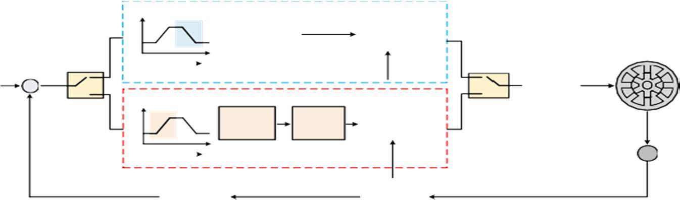
When the hybrid vehicles are in the deceleration or braking state, the engine works normally and drives the generator tocharge the battery pack. At this time, the SRM works in the power generation state to recover the braking energy Chopped current control (CCC), angular position control (APC), and chopper voltage control (CVC) are the three fundamental control techniques for SRM [30]. APC is appropriate for motors operating in high-speed mode, whereas CCC is appropriate for motors operating in low-speed mode. The speed range of the SRM created in this paper is broad. CVC, also known as voltage PWM control, can satisfy the demands of a larger speed range. range and is employed in this paper with a constant frequency of witching. Figure 5 illustrates the system's control strategy schematic. APC is employed in the breaking state, and the phase current of the braking operation is mostly established in the negative slope of the inductance. The turn-on angle and turn-off angle can be changed to alter the braking effect and the effectiveness of energy feedback during braking.
ISSN: 2321-9653; IC Value: 45.98; SJ Impact Factor: 7.538
Volume 11 Issue III Mar 2023- Available at www.ijraset.com
E. Static Charging
For hybrid vehicles with large battery capacity, charging by the first two methods may not be able to fully charge the battery and meet the requirements of a long journey. Therefore, it is possible to charge the hybrid car when necessary. Three-phase power can be linked to the system and the three-phase rectifier can give power to the system when the SRM is at rest. The BMs that need to be charged can be charged with the use of the asymmetric half bridge.
III. FUZZY CONTROLLER
A. Fuzzy Logic Controller
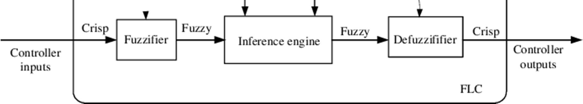
The truth value of variables in fuzzy logic, a type of many-valued logic, may be any real number between 0 and 1. When dealing with the idea of partial truth, where the truth value might range from totally true to completely false, this technique is used. In contrast, only the integer values 0 or 1 are permitted as the truth values of variables in Boolean logic. Fuzzy set theory refers to the use of approximate information, reasoning, and uncertainty to produce decisions. There are actually two key factors to consider when choosing a fuzzy logic controller, such as Modeling has adaptive properties and can be created for non-linear systems. The configuration of the fuzzy logic controller is shown in the image. In fuzzy logic, specifying a system's operating characteristics is straightforward.
B. Fuzzification
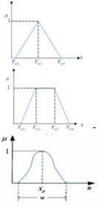
The process of mapping the fuzzy membership function with numerous measured crisp inputs is known as fuzzification. Also, it turns the input data into a useful value. As a result, this appropriate value is regarded as a label for fuzzy sets. Scale mapping is also performed during fuzzification. Transfer of input variables to the appropriate discourse universe occurs during scale mapping. The graphic depicts the bell, triangular, and trapezoidal membership functions for fuzzy membership

ISSN: 2321-9653; IC Value: 45.98; SJ Impact Factor: 7.538
Volume 11 Issue III Mar 2023- Available at www.ijraset.com
C. Fuzzy Inference
Any fuzzy logic system must have a fuzzy inference system. In order to discover the output that corresponds to crisp inputs, it makes use of fuzzy set theory, IF-THEN rules, and fuzzy reasoning. Logic connectives such as and or are used to connect the conditions in IF-THEN rules.
FIS Characteristics
1) Using the fuzzy membership function, one can map the crisp value into the fuzzy value.
2) Get crisp value from the operation
3) Use the fuzzy rule base's IF-THEN rules to apply fuzzy output.
4) Use defuzzification techniques to transform fuzzy output into crisp
D. Defuzzification
In defuzzification, given fuzzy sets and related membership degrees, a quantified output in crisp logic is produced. A fuzzy set is mapped to a crisp set using this procedure. Usually, fuzzy control systems require it. These systems will contain a number of rules that combine a variety of factors into a result that is fuzzy, or one that can be defined in terms of membership in fuzzy sets. Reduce Pressure (15%), Sustain Pressure (34%), and Increase Pressure (72%) are some examples of rules that determine how much pressure to apply. Defuzzification is the process of translating the fuzzy set membership degrees into a precise choice or real value that can be input into the computation.
Internally, crisp sets are transformed to fuzzy sets. The most straightforward but least effective defuzzification technique is to pick the set with the highest membership in this case, "Add Pressure" because it has a 72% membership ignore the others, and convert this 72% to some other value. This method has the drawback of information loss. In this instance, the rules that called for lowering or maintaining pressure might as well not have existed
E. Rule- Base
Fuzzy rule-based systems, broadly speaking, are rule-based systems where fuzzy sets and fuzzy logic are utilized as tools for capturing various types of knowledge about the current problem as well as for modeling the interactions and relationships between its variables.
Language is neither spoken or understood by computers in the same way that it is by people. A machine cannot immediately understand the subtleties of semantics, diction, and intent. Instead, humans provide the computer with a set of guidelines that specify how to handle incoming data. However, when considering rule-based systems, the machine learning technique is frequently regarded to be independent even if there are certain types of rule-based systems in which the computer assists in the definition of its rules.
Applications
1) Rule-based systems can be utilized for natural language processing, lexical analysis, compilers, interpreters, and computer programs.
2) Rule-based programming makes an effort to derive execution directives from a base collection of facts and rules. Compared to imperative language programming, which sequentially outlines execution steps, this approach is more indirect
F. Data Base
The knowledge about all fuzzy input-output relationships is kept in the fuzzy knowledge base. It also comprises the membership functions that provide the output variables for the controlled plant and the input variables for the fuzzy rule base. A computer program known as a knowledge-based system (KBS) combines reasoning and a knowledge base to resolve complicated issues. The phrase is inclusive and can be used to describe a wide range of systems. The attempt to formally describe knowledge and a reasoning mechanism that enables it to infer new knowledge are the two things that tie all knowledge-based systems together. An inference engine and a knowledge base are the two differentiating characteristics of a knowledge-based system. The knowledge base, which is the initial component, contains information about the world, frequently in the form of a subsumption ontology. In addition to a subsumption ontology, other popular methods include frames, conceptual graphs, and logical statements.
ISSN: 2321-9653; IC Value: 45.98; SJ Impact Factor: 7.538
Volume 11 Issue III Mar 2023- Available at www.ijraset.com
IV. SIMULATION AND EXPERIMENT
A. Simulation Results
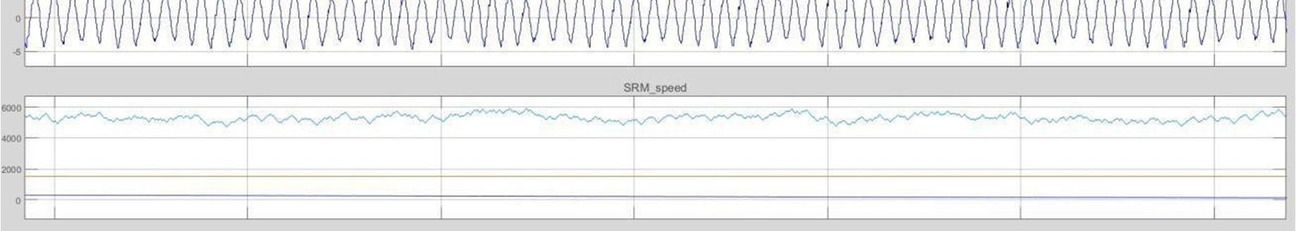
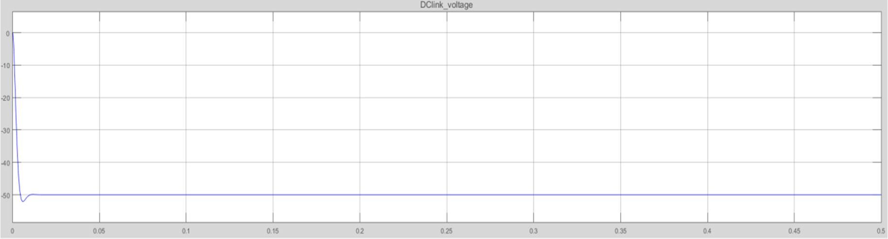
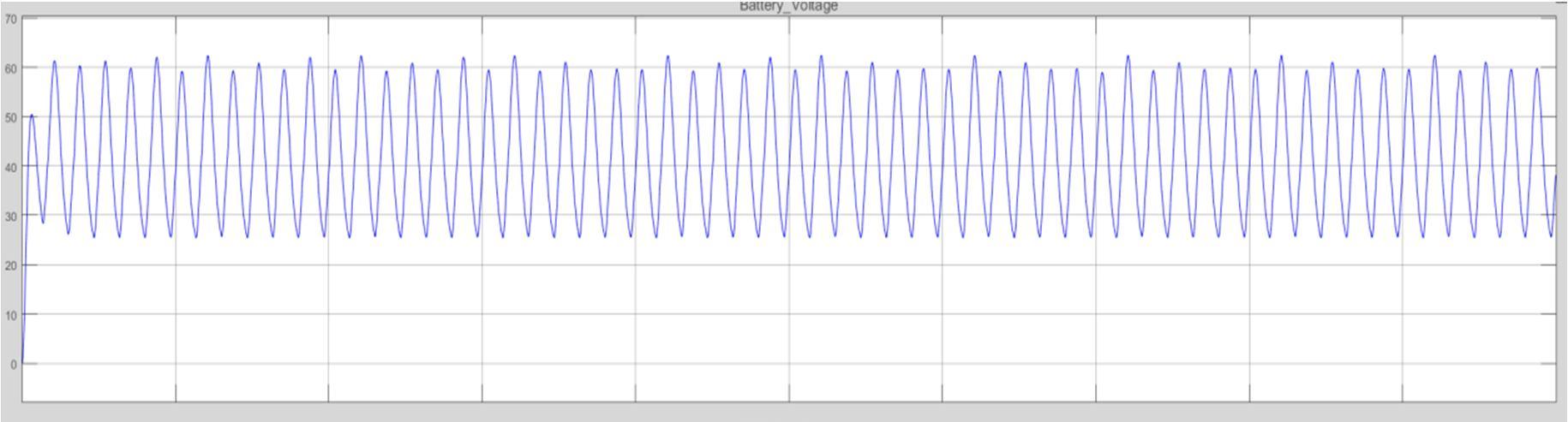
The simulation model of the converter is created in Matlab/Simulink, and the parameters of the SRM model are displayed in Table I in order to confirm the viability of the power converter presented in this paper. In this simulation, the rectifier stabilises the generator output voltage at 50V, while a single battery module's voltage is set at 12V. For the purposes of the simulation analysis, four BMs are linked in series with a 1Nm load torque.

Parameters Of Multilevel Converter Drive System
B. Existing
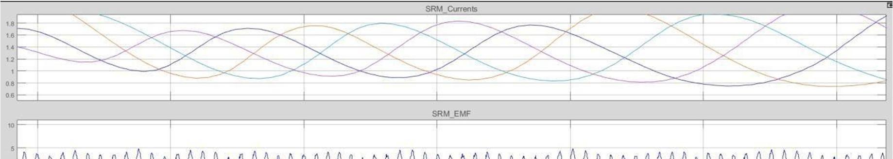
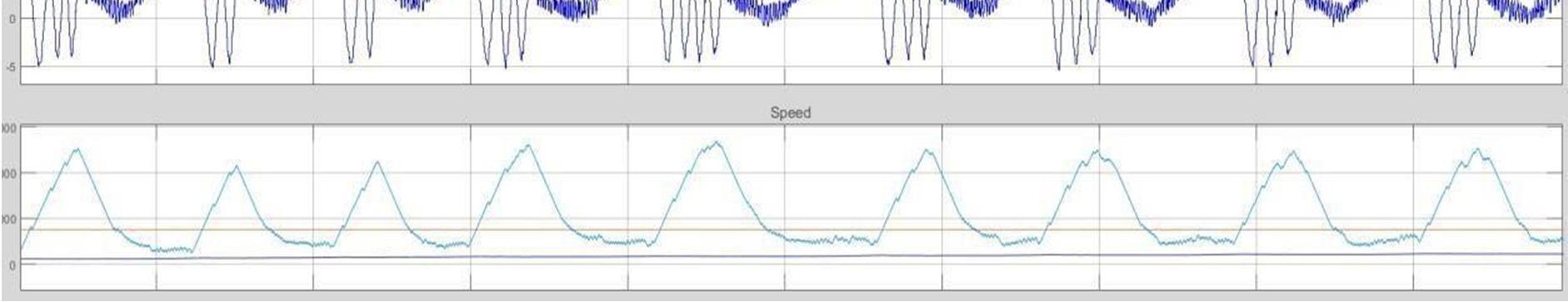
The waveform created when the battery pack and generator are both energised. the waveform of the generator and four battery modules simultaneously supplying power. waveform when two additional batteries are used in the charging mode, along with the generator, two BMs, and two other batteries. Each switching tube of the asymmetrical half-bridge receives the same PWM signal injection while the devices of each BM are switched off. The system provides electricity to the four windings by turning on the eight switch tubes. The electrical energy held in the windings is fed back to the front end to charge the battery when the eight switch tubes are switched off. Figure 18 displays the battery current waveform as well as the current waveform for each winding.

C. With Fuzzy
In fig, the power source is handled by all four BMs. The waveform shows that the system bus voltage is the total of the voltages for the four batteries, which are cycled through rounds of charging and discharging. The following are the results of a survey conducted by the National Institute of Standards and Technology. The phase-A winding's voltage is multilevel due to the presence of the freewheeling overlap region. Three BMs are regularly charged and discharged, and a fourth BM is only charged when the vehicle is freewheeling.
ISSN: 2321-9653; IC Value: 45.98; SJ Impact Factor: 7.538
Volume 11 Issue III Mar 2023- Available at www.ijraset.com
The phase-A excitation voltage will rise when the phase-D current in the freewheeling period exceeds the phase-A excitation current. Because phase A's freewheeling current is higher than phase B's excitation current, phase A's voltage also rises during the freewheeling phase. Thus, quick stimulation and quick freewheeling are made possible. In order to achieve SOC balance for the BMs, the bus voltage can be changed flexibly to suit the requirements of the system and the power of each BM can be used to control whether or not each BM is charged during the freewheeling stage. Stator voltage and current models are used to regulate the estimation of the stator flux.
V. CONCLUSIONS
Climate and the environment. This research paper uses MATLAB software to create a switched reluctance motor model with a fuzzy logic controller. The model is successfully tested by displaying the torque and speed values graphically. In particular for motion control, switched reluctance motors have a much higher potential.
High efficiency in challenging conditions, such as a dusty environment and high temperatures, for a switched reluctance motor. Through the use of MATLAB software, the SRM with fuzzy logic controller is developed. We preferred fuzzy logic controller in SRM drives based on the innovative converter because PI controller has some drawbacks.